Contributors
- Romain Delpoux, 2021.11.04
- Loic Queval, 2021.11.05
- Adrien Prévost, 2021.11.05
- Luiz Villa, 2021.11.07
- Antoine Boche, 2021.11.08
Tutorial Boost
The goal of this tutorial is to explore how to make a boost with the O2 power converter. You will activate the boost and its associated pid parameters, which will automatically drive the duty cycle of the power converter. For this tutorial we will build on your knowledge of communication, measurement, PWM and PID while replacing the buck related elements by their boost equivalent. We will start from the Hardware Setup 3 Tutorial project.
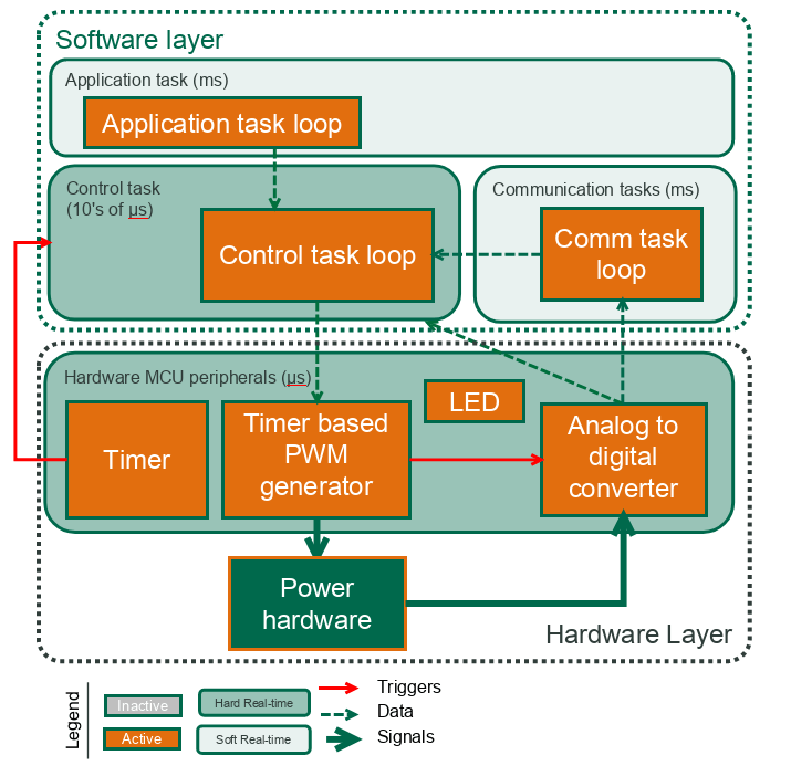
The blocks that are active in this tutorial are shown in the figure below.
Required hardware
- O2
v_1_1_2 - STLinkV3
- PC (windows or linux)
- power supply (40 V, 2 A)
Create the project
- We will create the project by copying the communication project in a new branch, that will be called boost. In the terminal,
- On the bottom menu, check that you are now in the boost branch.

- Check the libraries
In src/main.cpp, check that we load the owntech.ini libraries and the OS drivers:
//-------------OWNTECH DRIVERS-------------------
#include "opalib_pid_voltage.h"
#include "opalib_quick_start.h"
#include "data_conversion.h"
#include "data_acquisition.h"

//------------ZEPHYR DRIVERS----------------------
#include "zephyr.h"
#include "string.h"
#include "drivers/gpio.h"
#include "sys/printk.h"
#include "console/console.h"
- Define the hardware by software !
In src/main.cpp, change the buck_mode variable to false to activate the boost mode.
In src/main.cpp, do not change anything to the setup_hardware() function.
- Define the communication task and the communication menu
In src/main.cpp, replace the menu_mode by the menu_mode below to create a new BOOST control mode. This will keep the previous modes available if necessary.
enum menu_mode //LIST OF POSSIBLE MODES FOR THE OWNTECH CONVERTER
{
    IDLEMODE =0,
    POWERMODE,
    BUCKMODE,
    BOOSTMODE,
};
In src/main.cpp, the functions setup_communication_task() remains unchanged.
The loop_communication_task() now has to change the menu to treat the buck mode case. Replace
void loop_communication_task(void *arg1, void *arg2, void *arg3)
{
    while(1) {
        menu();
        received_serial_char = console_getchar();
        switch (received_serial_char) {
            case 'i':
                printk("idle mode\n", received_serial_char, received_serial_char);
                mode = IDLEMODE;
                break;
            case 'p':
                printk("power mode\n", received_serial_char, received_serial_char);
                mode = POWERMODE;
                break;
            case 'b':
                printk("buck mode\n", received_serial_char, received_serial_char);
                mode = BUCKMODE;
                break;
            case 't':
                printk("buck mode\n", received_serial_char, received_serial_char);
                mode = BOOSTMODE;
                break;
            case 'u':
                printk("Duty Cycle UP: %f\n", duty_cycle);
                duty_cycle = duty_cycle + duty_cycle_step;
                break;
            case 'd':
                printk("Duty Cycle DOWN: %f\n", duty_cycle);
                duty_cycle = duty_cycle - duty_cycle_step;
                break;
            default:
                break;
        }
    }
}
The menu() function will have to be changed to reflect the new commands now available to the user. Add the code below to do so.
void menu() {
    printk(" _______________________________________________\n");
    printk("|\t Power conversion Example \t\t|\n");
    printk("|\t ------- menu -------    \t\t|\n");
    printk("|\t press i : idle mode   \t\t\t|\n");
    printk("|\t press p : power mode  \t\t\t|\n");
    printk("|\t press u : DUTY CYCLE UP BY 5%   \t|\n");
    printk("|\t press d : DUTY CYCLE DOWN BY 5%  \t|\n");
    printk("|\t press b : ACTIVATE BUCK MODE  \t\t|\n");
    printk("|\t press t : ACTIVATE BOOST MODE  \t\t|\n");
    printk("|_______________________________________________|\n\n");
}- Define the application task
In src/main.cpp, add the following code to define the variables that will be used by the application task to print the Vhigh and V1_low measurement values:
//--------------USER VARIABLES DECLARATIONS----------------------

static float32_t voltage_reference = 60;
static int cpt_step = 0;
In src/main.cpp, in the function setup_application_task(), do not modify anything. This task will link your application task to a thread which will be executed automatically.
In src/main.cpp, in the function loop_application_task(), add the following code to define the application task. In this example, it will turn the LED on and off depending on the mode chosen by the user. When the led is ON the O2 converter will print the value of Vhigh and V1low on the Serial Monitor.
void loop_application_task(void *arg1, void *arg2, void *arg3)
{
    while(1){

        if(mode==IDLEMODE) {
            // application loop in idle mode goes here
            gpio_pin_set(led_pin_spec.port,led_pin_spec.pin,0);

        }else if(mode==POWERMODE) {
            // application loop in power mode goes here
            gpio_pin_set(led_pin_spec.port,led_pin_spec.pin,1);
            printk("Vhigh value: %f ||", Vhigh_value);
            printk("V1low value: %f \n", V1_low_value);
        }else if(mode==BUCKMODE) {
            // application loop in buck mode goes here
            gpio_pin_set(led_pin_spec.port,led_pin_spec.pin,1);
            if(cpt_step==10)
                voltage_reference = 15;
            if(cpt_step==20) {
                voltage_reference = 10;
                cpt_step=0;
            }
            printk("V1 balue: %f\n",V1_low_value);
            cpt_step ++;
        }else if(mode==BOOSTMODE) {
            // application loop in boost mode goes here
            gpio_pin_set(led_pin_spec.port,led_pin_spec.pin,1);
            if(cpt_step==10)
                voltage_reference = 70;
            if(cpt_step==20) {
                voltage_reference = 60;
                cpt_step=0;
            }
            printk("Vhigh value: %f\n",Vhigh_value);
            cpt_step ++;
        }

        k_msleep(100);
    }
}
- Define the control task
In src/main.cpp, in the function setup_control_task(), we will use the same PID parameters from the previous tutorial. Replace the setup_control_task() with the code below so the boost mode is setup correctly.
void setup_control_task(){
    // control loop setup goes here
    uint32_t control_task_duration = 50;
    float32_t kp = 0.000215;
    float32_t ki = 2.86;
    float32_t kd = 0.0;


    opalib_quick_start_init(loop_control_task, control_task_duration);
    opalib_pid_voltage_init_boost(voltage_reference, kp, ki, kd, control_task_duration);
    opalib_quick_start_launch_task();
}
In src/main.cpp, in the function loop_control_task(), replace it by the code below. This will allow the BOOSTMODE to be handled by the function while keeping compatibility with previous cases.
void loop_control_task()
{
    if(mode==IDLEMODE) {
        pwm_enable = false;
        opalib_pid_voltage_stop();
        gpio_pin_set(led_pin_spec.port,led_pin_spec.pin,0);

    }else if(mode==POWERMODE || mode==BUCKMODE || mode==BOOSTMODE) {
        //creates variables that receives the number of measurements that are returned by the low-level api
        uint32_t v1_low_count;
        uint32_t v_high_count;

        // Creates two buffers that receives the data from the data acquisition module

        //Vhigh data acquisition
        uint16_t* v_high_buffer = data_acquisition_get_v_high_values(&v_high_count);

        if (v_high_count){ //if data was received it gets converted
            uint32_t raw_value = v_high_buffer[v_high_count - 1];
            Vhigh_value = data_conversion_convert_v_high(raw_value);
        }

        //V1low data acquisition
        uint16_t* v1_low_buffer = data_acquisition_get_v1_low_values(&v1_low_count);

        if (v1_low_count){ //if data was received it gets converted
            uint32_t raw_value = v1_low_buffer[v1_low_count - 1];
            V1_low_value = data_conversion_convert_v1_low(raw_value);
        }

        //Activates the PWM if it was off
        if(!pwm_enable) {
            gpio_pin_set(led_pin_spec.port,led_pin_spec.pin,1);
            pwm_enable = true;
            opalib_pid_reset_state();
            opalib_pid_voltage_start();
        }

        //Sends the PWM to the switches
        if(mode==BUCKMODE) duty_cycle = opalib_pid_voltage_pid_calculation(voltage_reference, V1_low_value);
        if(mode==BOOSTMODE) duty_cycle = opalib_pid_voltage_pid_calculation(voltage_reference, Vhigh_value);

        opalib_pid_voltage_pwm_update(duty_cycle);
    }
}- Connect hardware
Now we will connect OwnTech’s O2 to the power supply and to the PC.
- Connect the pins V1_low and V2_low together to the positive of the power supply. Connect both N1 and N2 together to the negative of the power supply.
- Connect the micro-JTAG connector of the O2 to the PC thanks to the STLinkV3. The leds PWR and COM should be ON.
- Switch on the power supply. The led2 of the O2 should be ON.
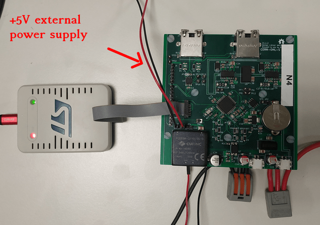
- !!! Warning !!! When operating in boost mode means voltage levels can go dangerously high. It is advised to feed the power converter with 5V from an external source and feed the low side with 20V.
The connection is shown in the figure below.
In the bottom menu, click on the Build icon
 . This will launch the compilation of the code. When the compilation is completed, you should see [SUCCESS] in the terminal.
On the bottom menu, click on the Upload icon
 . This will flash the compiled code on the microcontroller of the O2. When the process is completed, you should see [SUCCESS] in the terminal.
On the bottom menu, click on the Serial Monitor icon
 . Should print you a menu for you at first. When you press the
 bbutton on your keyboard, the output should converge to 10V.
When you press the p button on your keyboard, half of the high side voltage will appear on the low side. the LED will turn ON and Vhigh and V1low data will show on the terminal and half of Vhigh will appear at Vlow. Hit the "u" button to raise the duty cycle and the "d" button to lower it, you will see the ratio between input and output change following the buck converter behavior. Hit the i button to turn it the LED OFF and stop the data display.
Expected outputs
- The led1 of the O2 should start as off.
- The led1 of the O2 should turn on when you press the
pbutton. - The led1 of the O2 should turn off when you press the
ibutton. - The voltage ratio between Vhigh and V1low changes when you press either
uord. - The voltage will converge to 10V if you press
b. - The voltage will converge to 60V if you press
t.
That’s it!