Introduction
In order to control a power converter we need a fine way to get the measures we want when we want them. Hence you will learn here how to set the ADC on Matlab and CubeMX to trigger the measure at a chosen moment of the PWM period.
Prerequisites
Having the software presented in Getting started downloaded.
CubeMX settings
For this tutorial the settings were inspired by the example provided by ST in the .ioc model called G431_ADC_33_3kHz, It was designed for another board, so it needed to be a bit modified to work on the NUCLEO-g474RE however the Simulink file is compatible, so we will copy it in our project folder.. This model can be found at the following path : C:/MATLAB/STM32-MAT/stm32/STM32demos/Test/ADC/G431-Nucleo.
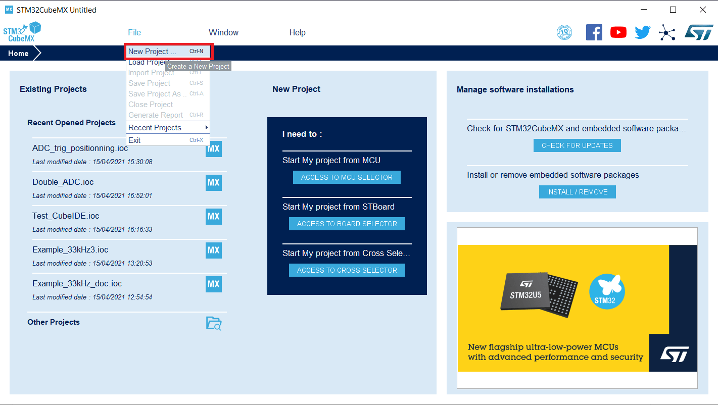
First we need to start a .ioc from scratch. When you launch the software select File>New project.
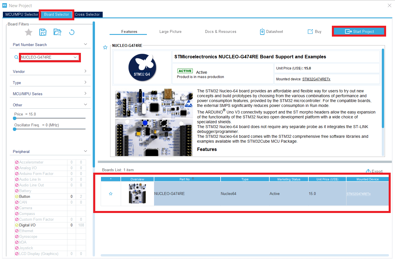
Then in the Board selector tab enter the reference of the NUCLEO board (G474RE), select it and you can start the project.
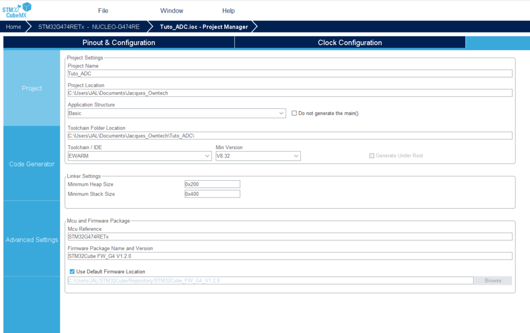
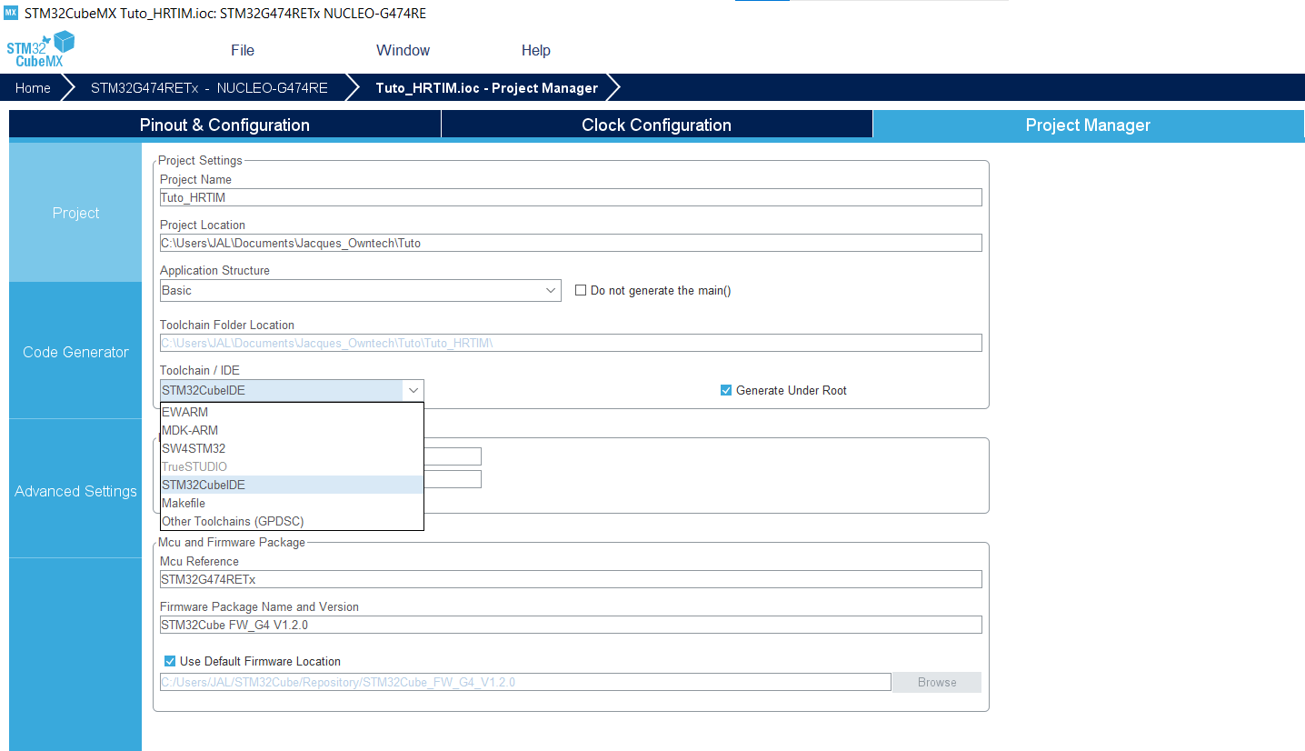
- In the tab Project Manager>Project set Toolchain/IDE to STM32CubeIDE.
ADC Parameters
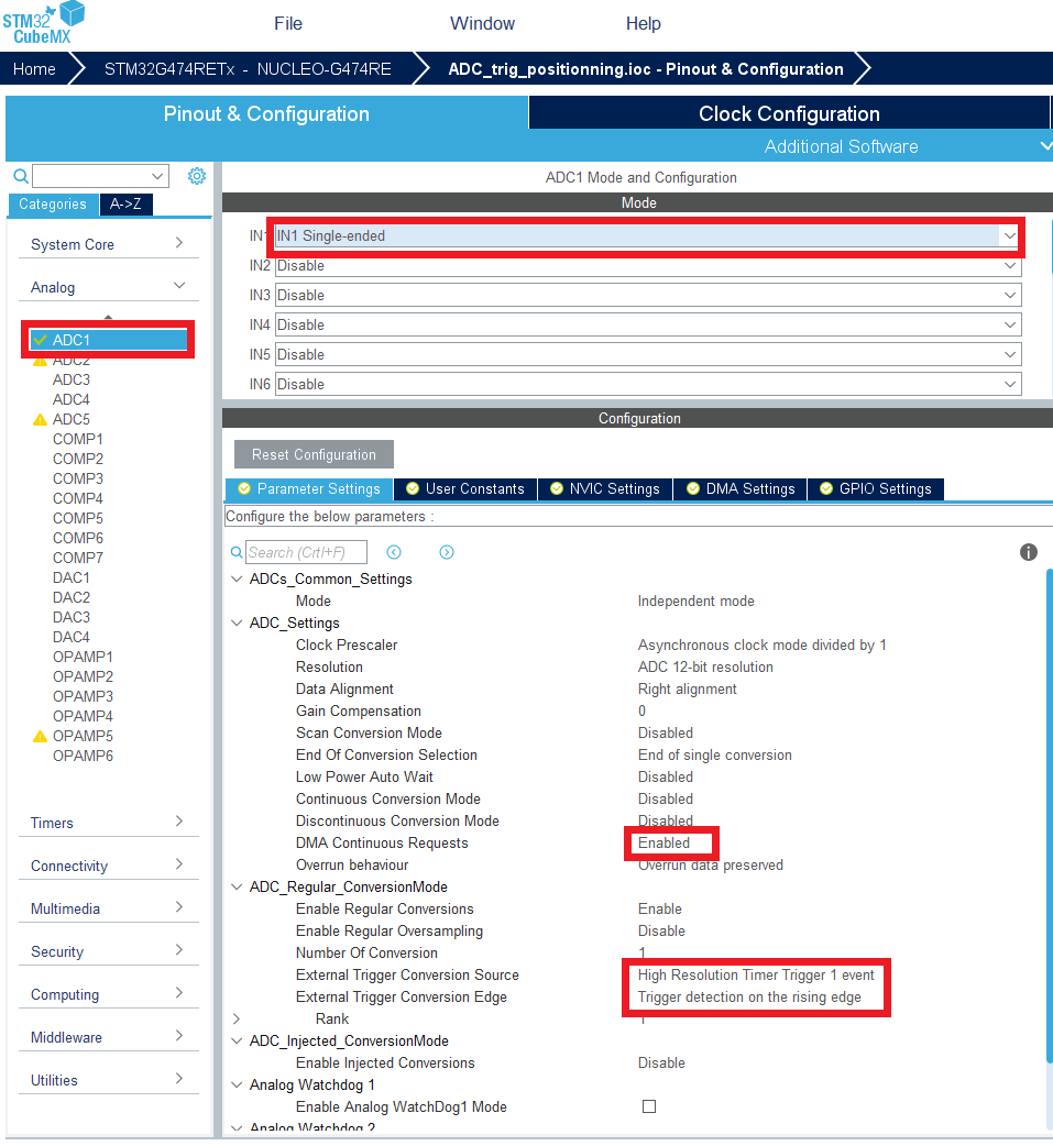
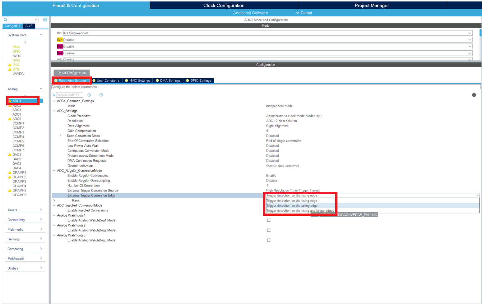
- Set IN1 to single-ended.
In the tab Parameter Settings
In ADC_Settings set DMA continuous requests to Enabled
In ADC_Regular_ConversionMode set External Trigger Conversion Source to High Resolution Timer Trigger 1 event and External Trigger Conversion Edge to Trigger detection on the rising edge.
In the DMA Settings tab
- Click on add and select ADC1, then in DMA Request Settings set Mode to Circular.
HRTIM Parameters
- Now unfold the Timers menu, go to HRTIM1 and enable Timer A by selecting TA1 output active .
In the DMA settings tab
- Click on add and select the circular mode.
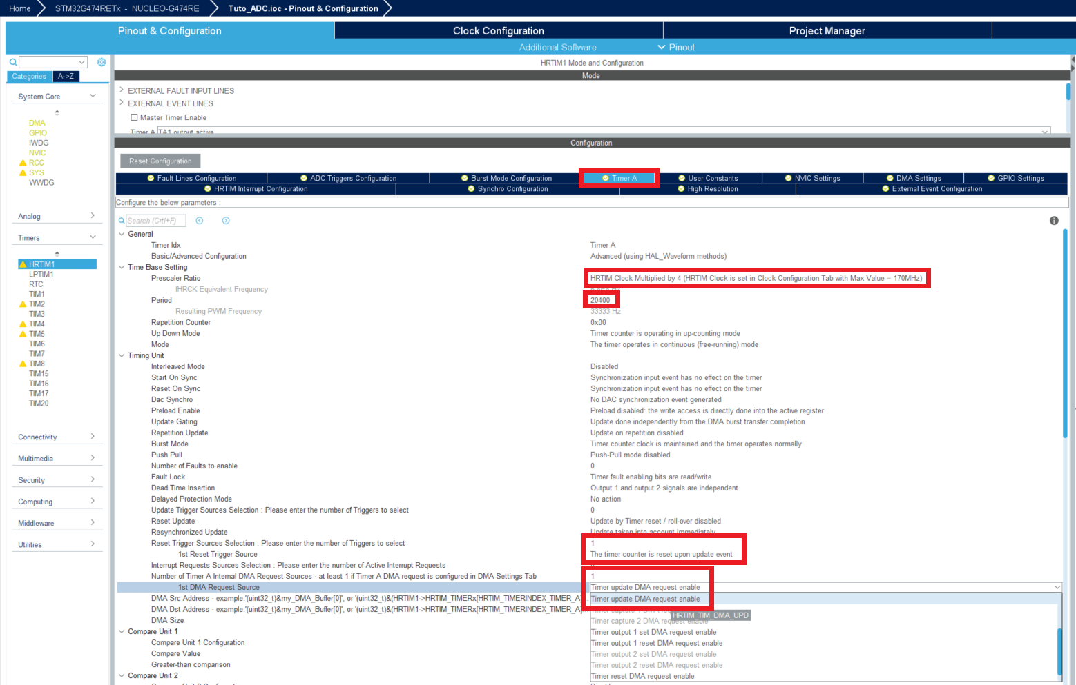
In the Timer A tab
Set the Prescaler Ratio to 4.
To set the PWM frequency to 33.3kHz, set period to 20400.
Set Reset trigger Source selection to 1 and 1st Reset Trigger Source to The timer counter is reset upon update event.
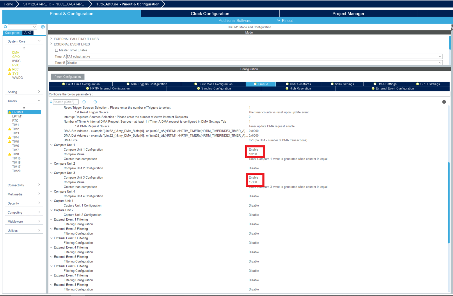
Below in the same tab, set Compare Unit 1 Configuration to Enable and enter a value in Compare Value. In fact this value doesn't matter because the real compare values of this timer will be set in the Simulink model.
Set Compare Unit 3 Configuration to Enable and enter a Compare value below.
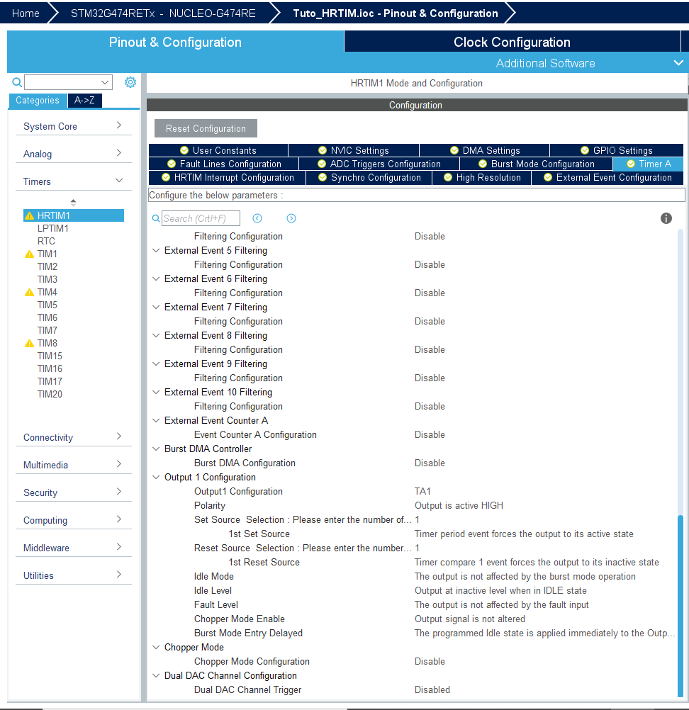
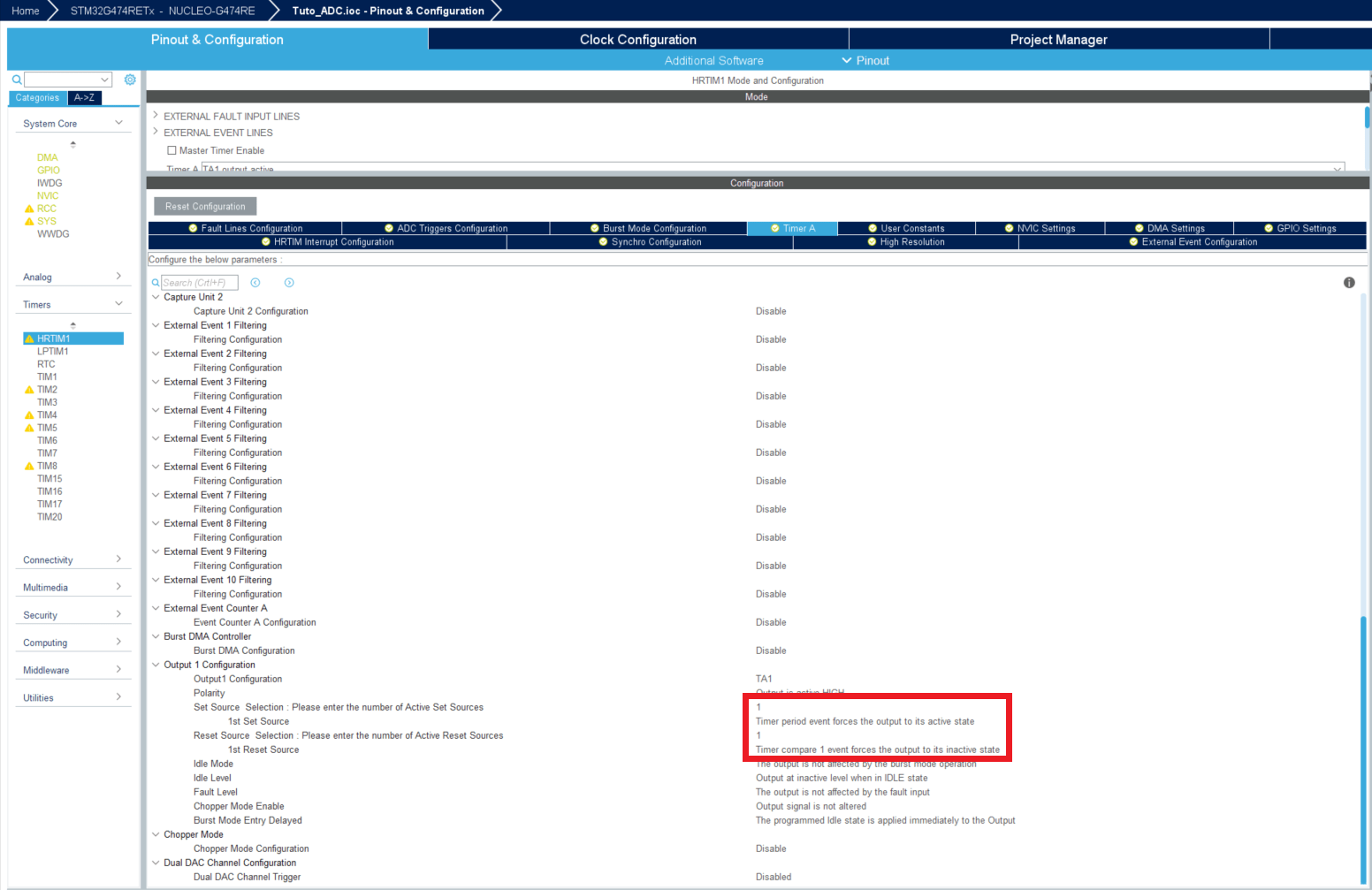
Set Set Source Selection to 1 and 1st Set Source to Timer period event forces the output to its active state.
Set Reset Source Selection to 1 and 1st Reset source Selection to Timer compare 1 forces the output to its inactive state.
In the ADC Triggers Configuration tab
Set ADC Trigger Configuration to Enable ADC Trigger 1.
Set Trigger Sources selection to 1 and 1st Trigger Source to ADC Trigger on Timer compare 3.
Don't forget to save your .ioc file before moving on
Simulink Settings
In order to save time (and avoid making mistakes) we will use the Simulink model given by ST that you can find at this path : C:\MATLAB\STM32-MAT\STM32\STM32demos\Test\ADC\G431-Nucleo\G431_ADC_33_3kHz
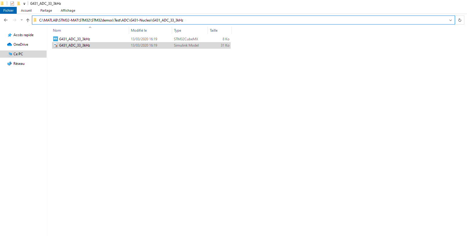
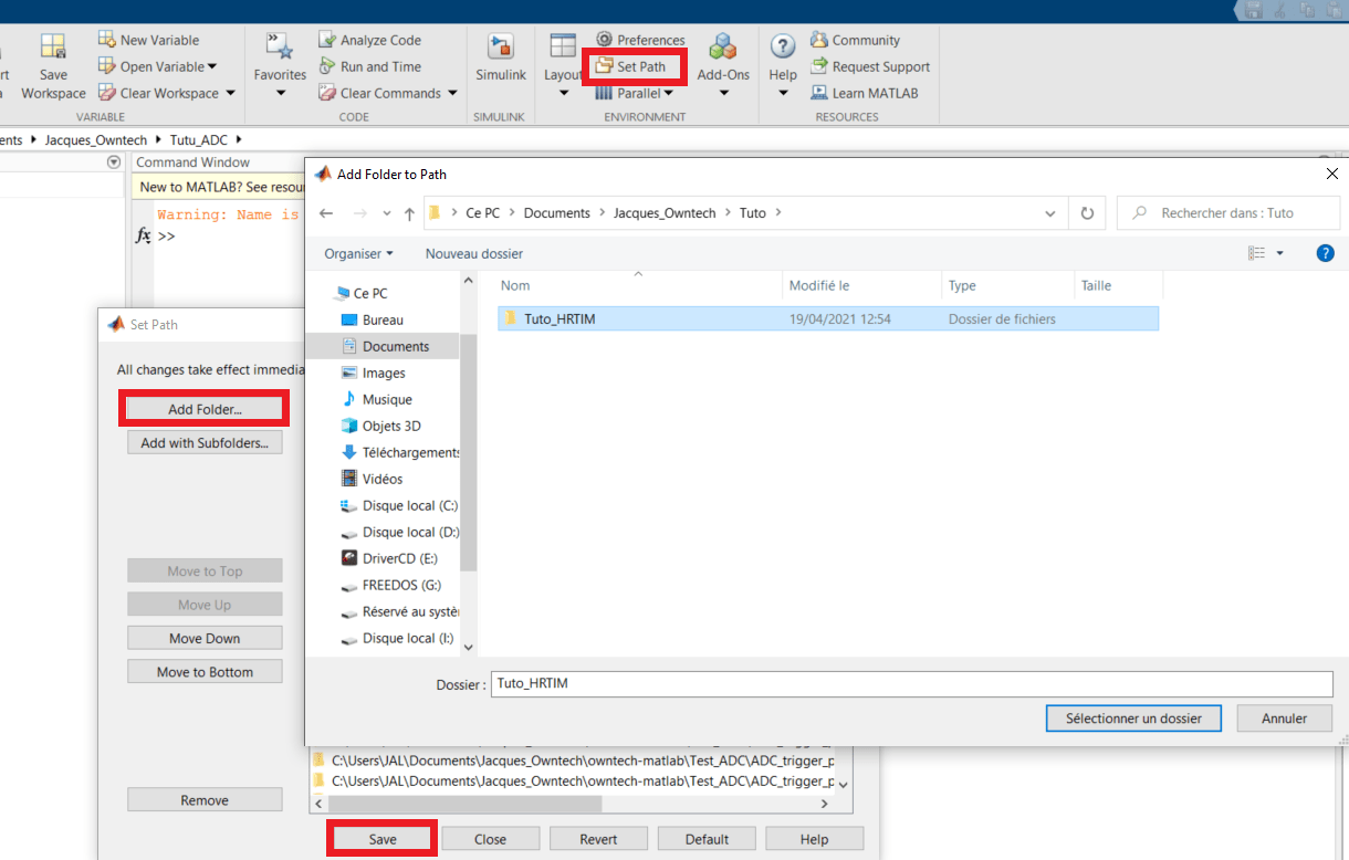
Copy and paste the simulink file in the same folder as the .ioc file that we just made, and now you can open Matlab.
Add the folder containing the Simulink model and the .ioc file to your Matlab path (cf Getting Started with Matlab and ST software)
Go in this very folder via Matlab before opening the simulink model in order to generate properly the code files.
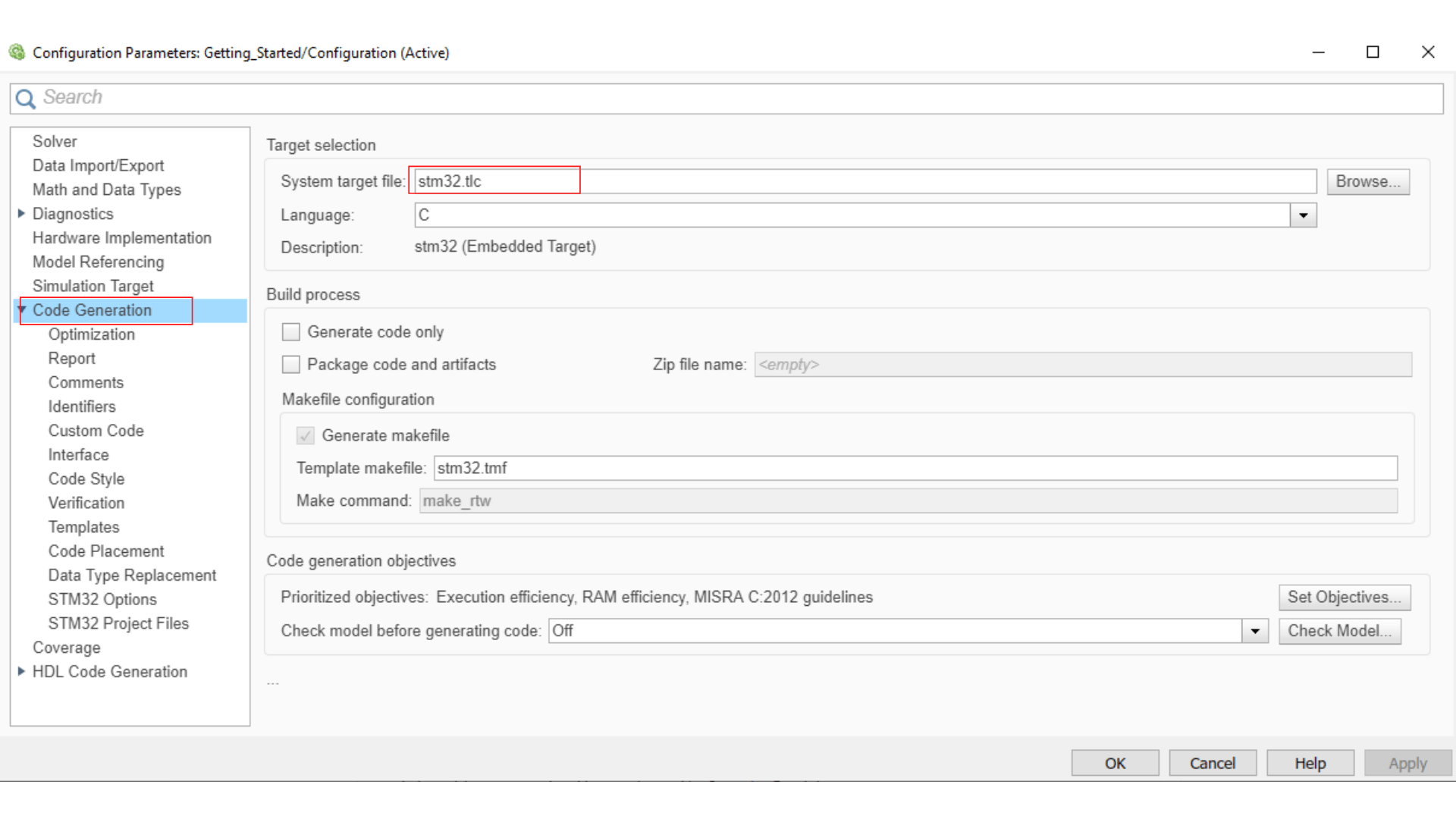
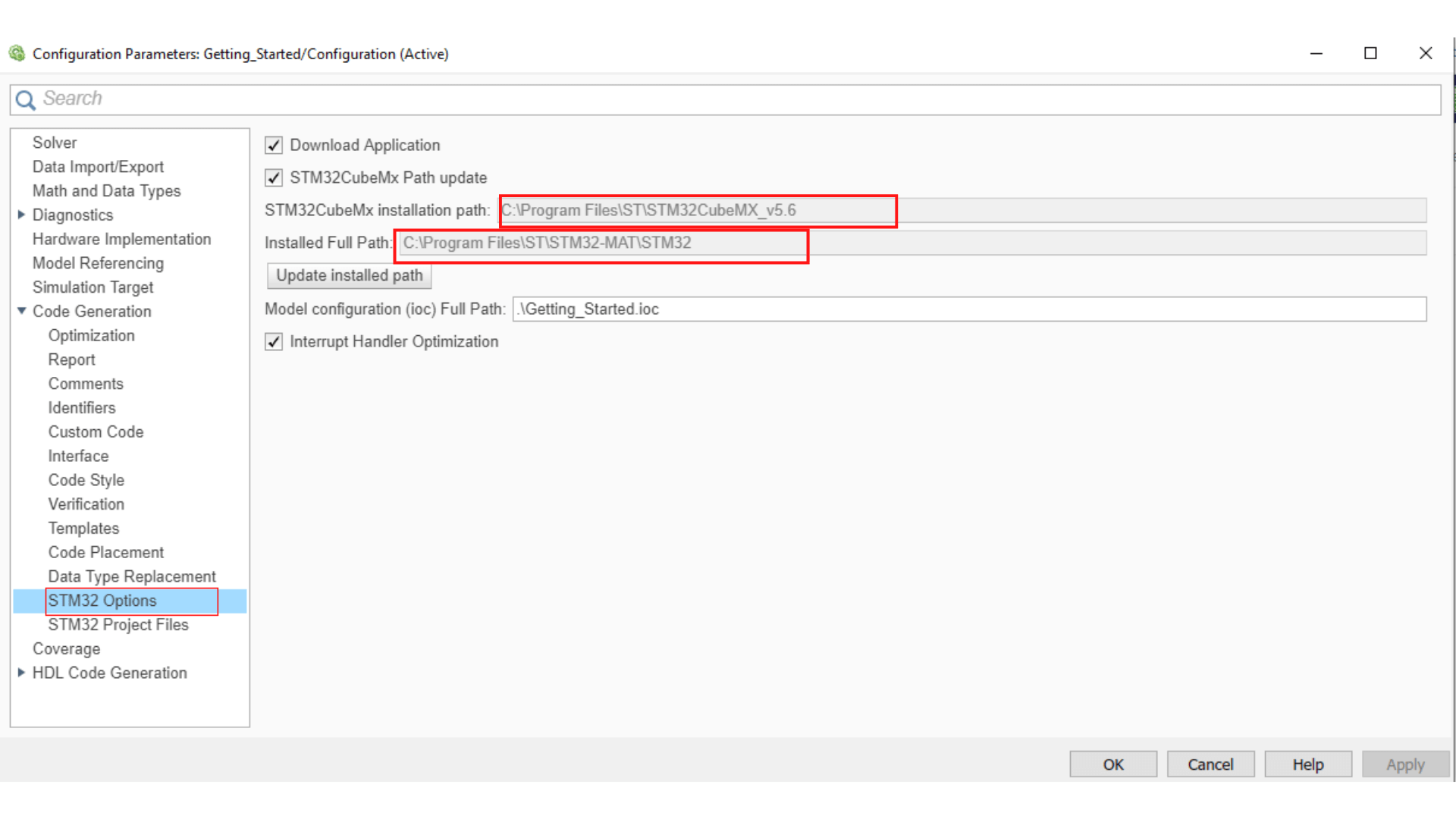
First thing to do when you get into the Simulink model is to double click the STM32 Configuration block to link the .ioc file to the Simulink with Select STM32 configuration file and then apply these changes.
- Then you can right click to get access Model configuration parameter and make the changes detailed in Getting started with Matlab and ST software
A .ioc file that has the same name as the one you rename can be created during this step, just delete it.
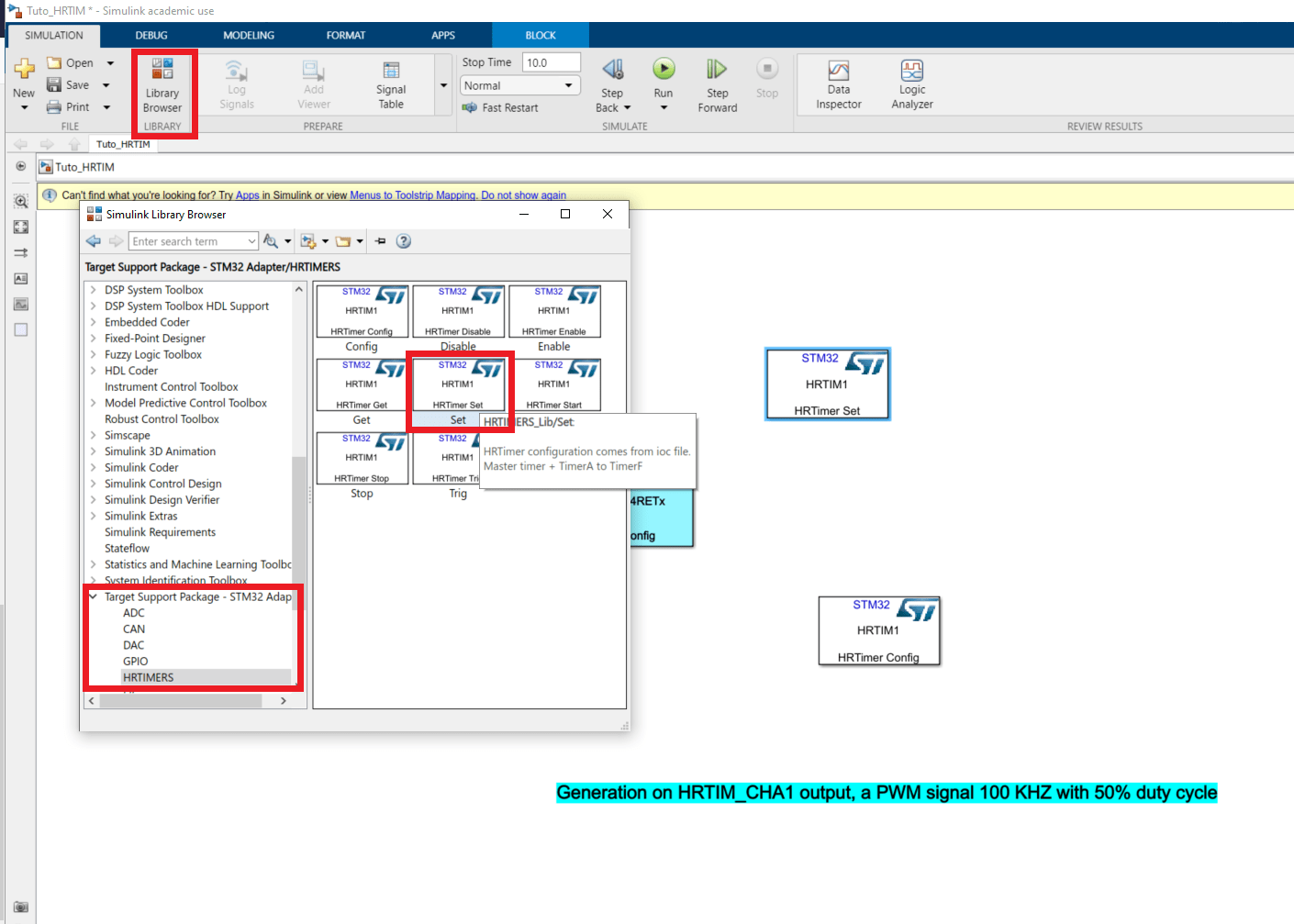
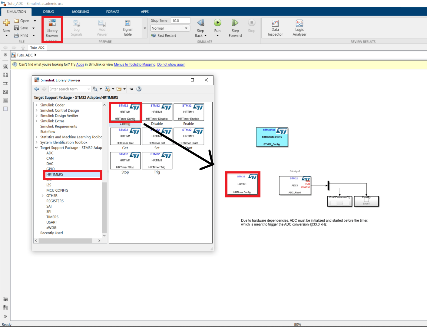
- Since this example was made for another board it uses TIM3 but we set the .ioc file with an HRTIM so we will delete this block and replace it with an HRTIM configuration block that you can find in Library browser>Target Support Package-STM32 Adapter>HRTIMERS.
- The HRTIM block should be all set with the parameters we typed in the .ioc file and double clicking on it should display this :
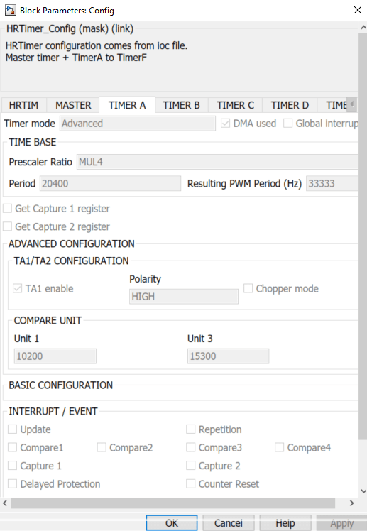
*If the settings aren't the ones you put into the .ioc file, you can try to tick and untick a box in the block configuration window and then apply in order to refresh. Sometimes the problem persists such as in this example where my ADC doesn't match my .ioc file settings.
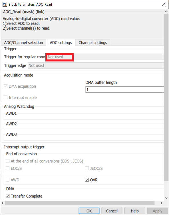
- In this case, go back to your .ioc file, change the settings whiches refuse to update and save.
- Return to your Simulink to see if it worked.
- Go back to CubeMX and set the parameter as you wanted to and after saving, it should be updated in the simulink model.
- In order to gain ergonomics we will set the Duty cycle and the ADC Trigger in the Simulink model, to do this add a HRTIMER Set block (from the same library as *HRTIMER Configuration), and in the tab Timer A tick the boxes Compare 1 is an input port and Compare 3 is an input port. This operation creates 2 input port in the HRTIM set block.
- In Library Browser>Commonly used blocks get two gain blocks and two constant blocks and arrange them as such.
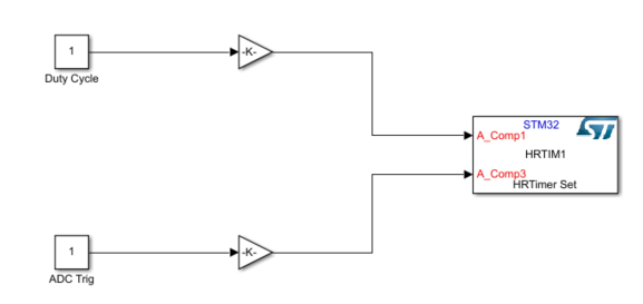
The top block will set the Duty Cycle and the bottom one will be the period ration at which the ADC is triggered. Hence if it is inferior to the duty cycle, the measure will be triggered when the PWM voltage is high and conversely.
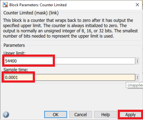
- Set the two gains to 20400 and in the tab Signal Attributes set Output Data type to uint16.
20400 is the number of counts during a period so multiplying it by the duty cycle will give to the HRTIM the number of counts before the reset.
- Set the two constants to decimal numbers between 0 and 1. In practical cases the duty cycle can't be too close to 1 or 0.
Don't forget to save your Simulink file before generating the code
- Now you are ready to generate the code with App>Embedded coder and then C code>Generate code.
The code generation can take a few minutes even for this simple example.
In STM32CubeIDE
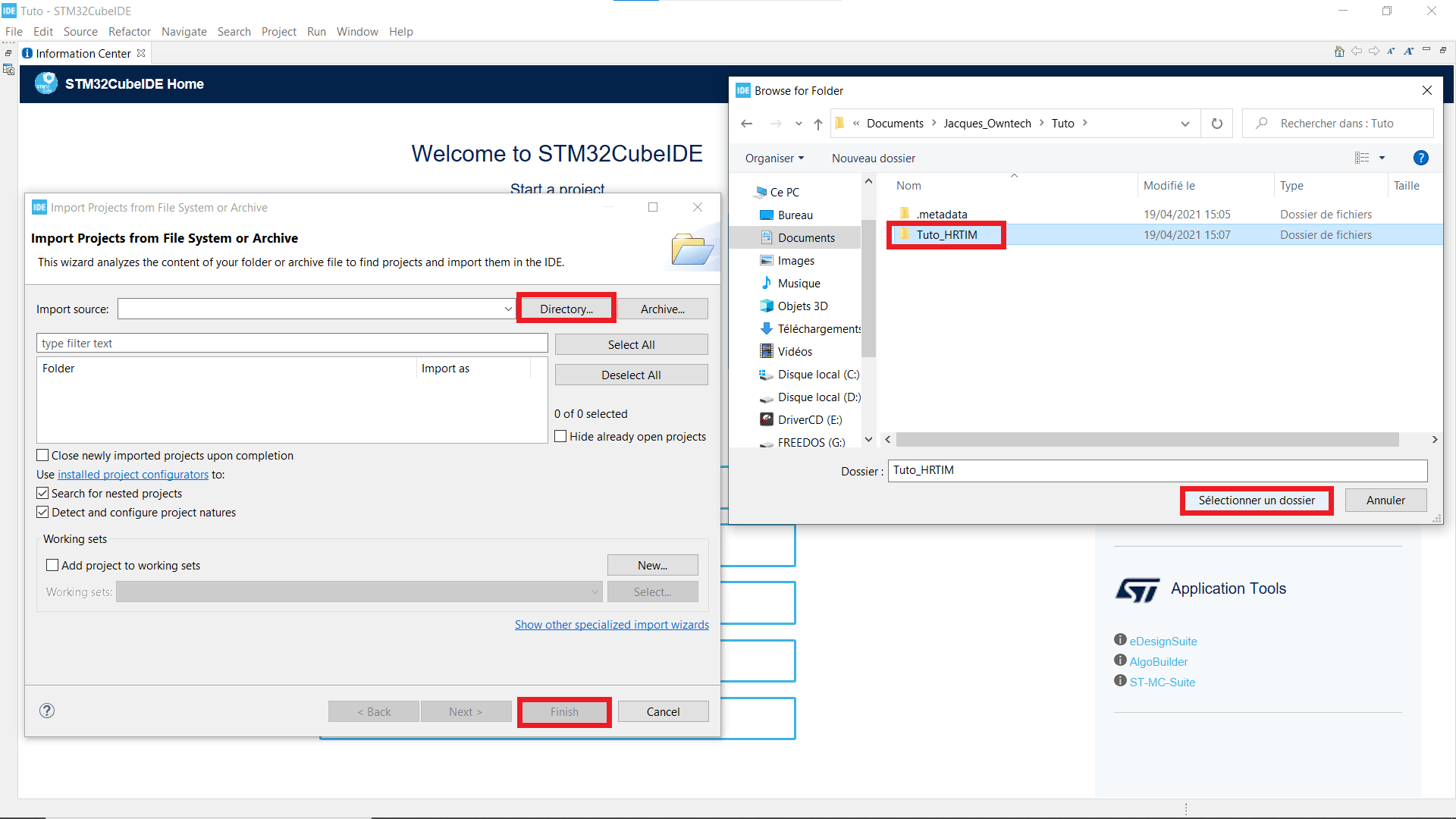
Open STM32CubeIDE in the workplace where your project is located.
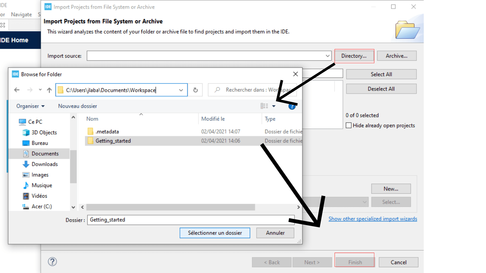
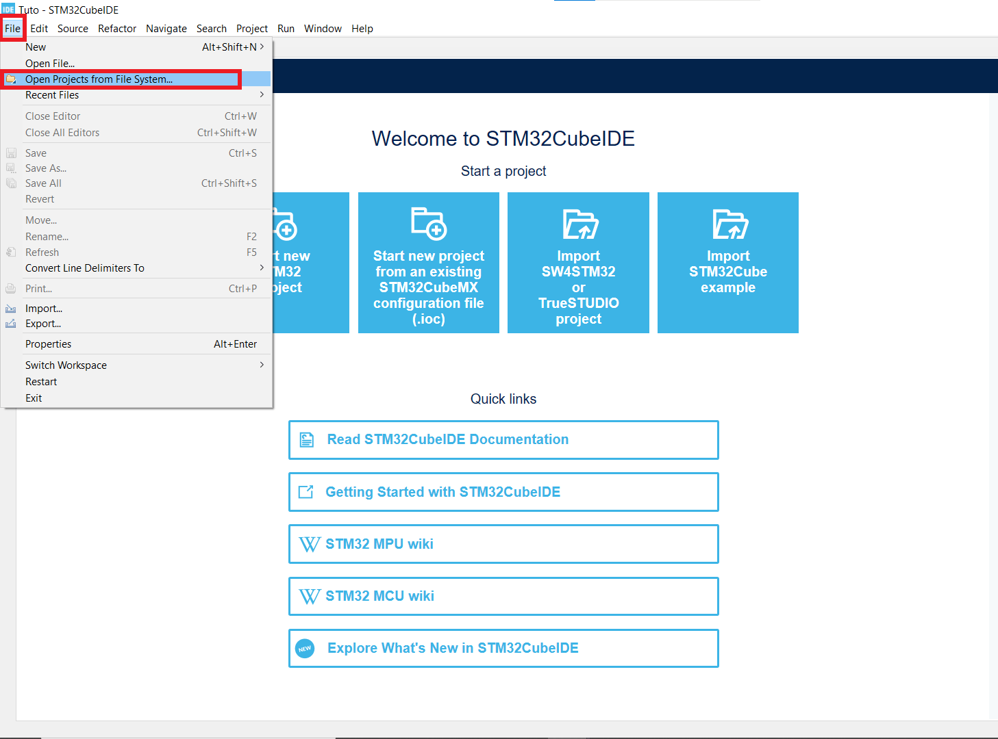
Open your project with File>Open project from file system
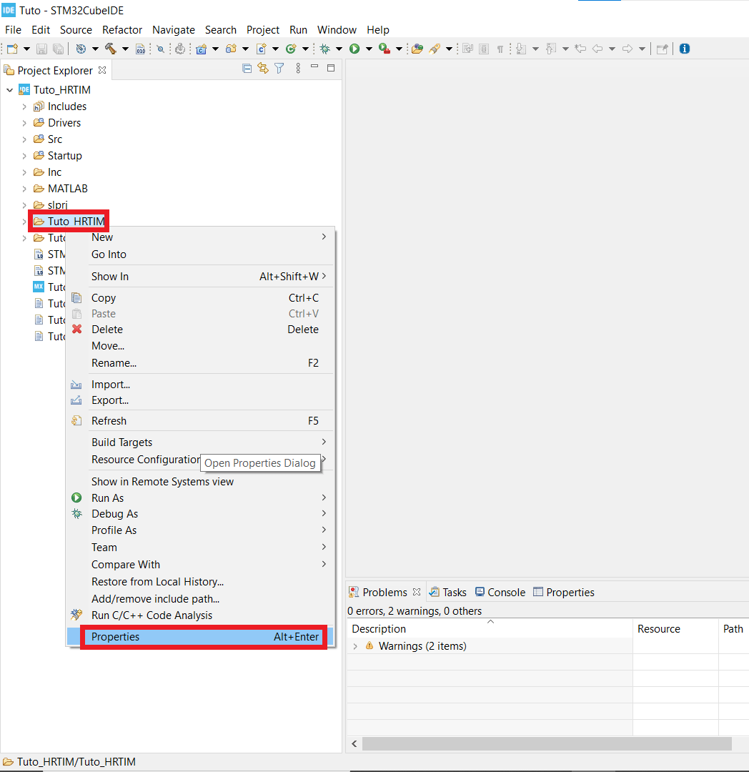
Right click on the folder that has the same name as your project and open the properties window.
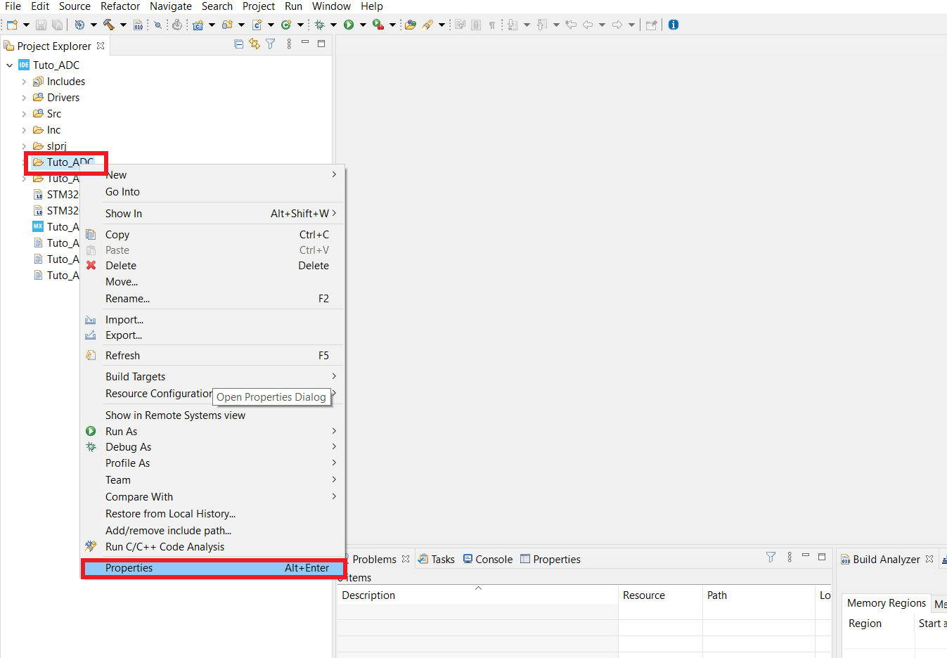
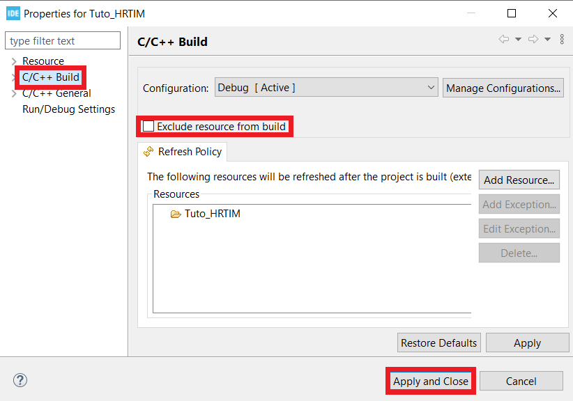
- In the C/C++ build tab untick the box that says Exclude resource from build
In order to test whether your code works or not you need to follow the evolution of some variables, fortunately the STM32CubeIDE debugger can help.
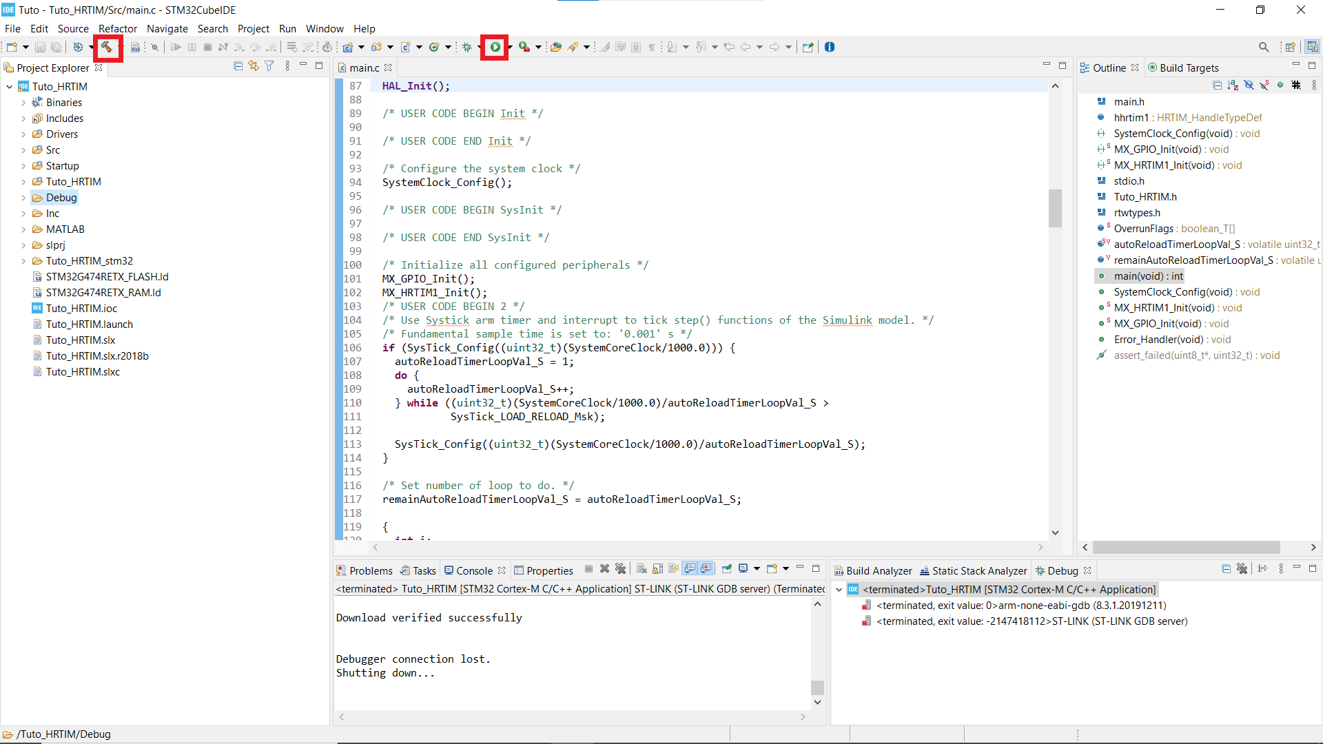
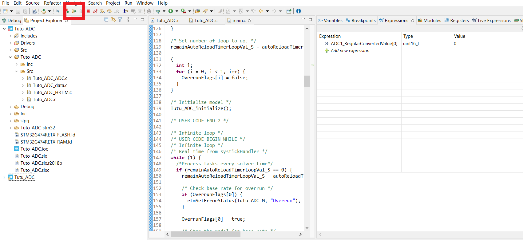
- In the folder named after your project name (in my case Tuto_ADC) find in Src the .c file named after your project.
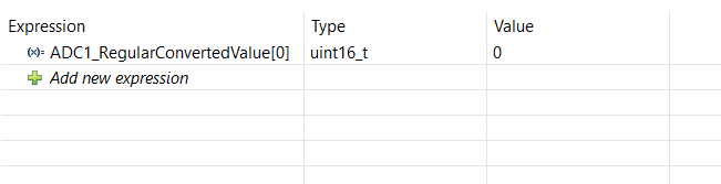
- Open it in order to find the variable ADC1_RegularConvertedValue[0] and copy it. This is the variable where the measure is stored.
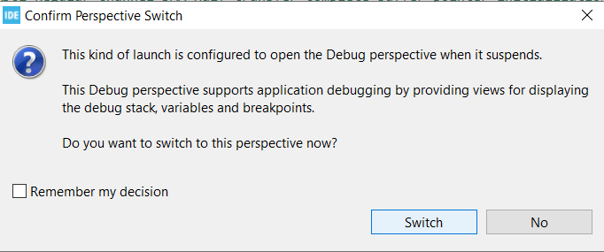
- You can now start the debug session, and this window should appear : select switch.
- Right click in the code window, choose Add watch expression and paste the variable name in the field. Now its value is accessible during the execution.
Hardware experiment
- Now that your code is compiled and ready to be debugged, plug your NUCLEO-G474RE to your computer and hit the resume button.
To see the value of the ADC acquisition, you need to pause the algorithm (with the pause button next to the resume button). So to make a good test, connect the ADC pin succesively to the ground and to the reference and then stop the execution to look at the value. When connected to the ground, it should be 0 and when connected to the reference it should be close to 4096.
Another experiment is to measure the PWM output of the HRTIM. Since the measures are driven by the HRtimer, they are all taken at the same moment of the period so they should all be equal (whether always 0 whether always 4096). If you reopen your Simulink file and change the ADC trig constant we created, you should observe that when it is below the duty cycle, the ADC measure is always (close to) 4096, and when it is above the duty cycle, the ADC measure is always 0.