Introduction
In order to drive a power converter with a Simulink model, it is necessary to be able to generate a PWM that can be driven by a Simulink model. In this tutorial I will show you a simple way to configure a Simulink file and a .ioc file to generate a variable PWM and to be able to observe it.
Prerequisites
To follow this tutorial, you need the following software :
- STM32CubeMX
- STM32CubeIDE
- Matlab with Simulink and Embedded coder
- STM32MatTarget
I detailed the installation and basic settings of these software in Getting started with Matlab and ST software.
CubeMX settings
In this tutorial, we will use the example provided by ST since they were made for NUCLEO-G474RE boards.
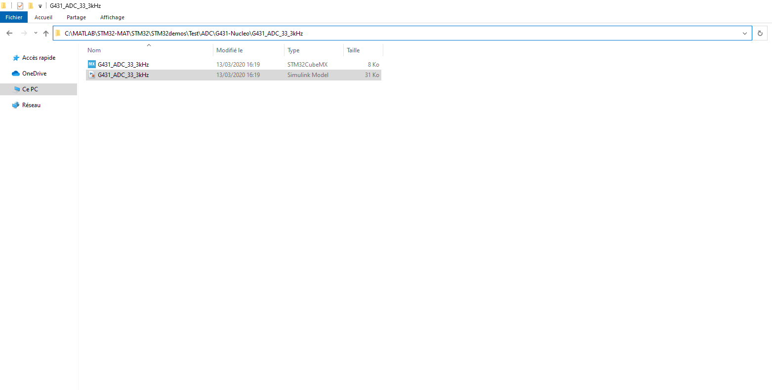
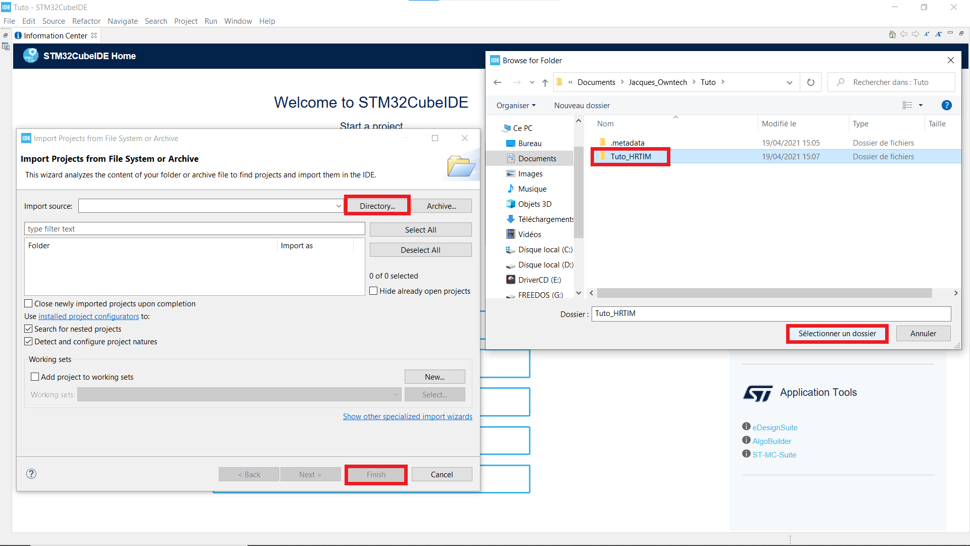
In a new folder, copy paste the .ioc and .slx files that you can find at the path : C:>MATLAB>STM-32MAT>STM32>STM32demos>Test>HRTimer>G474RE>HRTIM_Basic_SinglePWM ; in your working folder, and rename them like this folder.
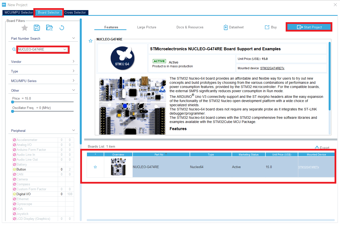
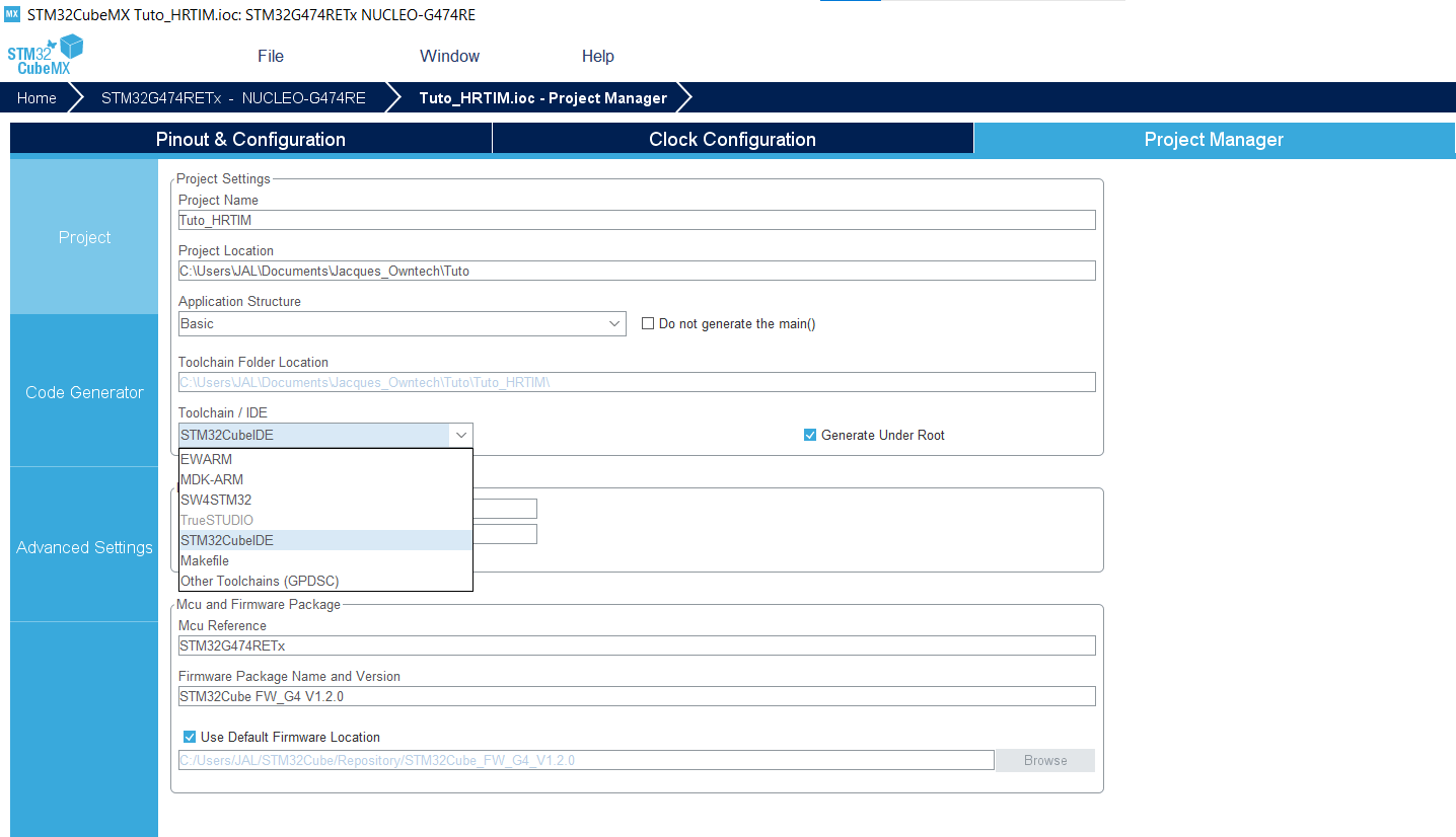
- In the tab Project Manager in Project, set Toolchain/IDE to STM32CubeIDE.
Simulink settings
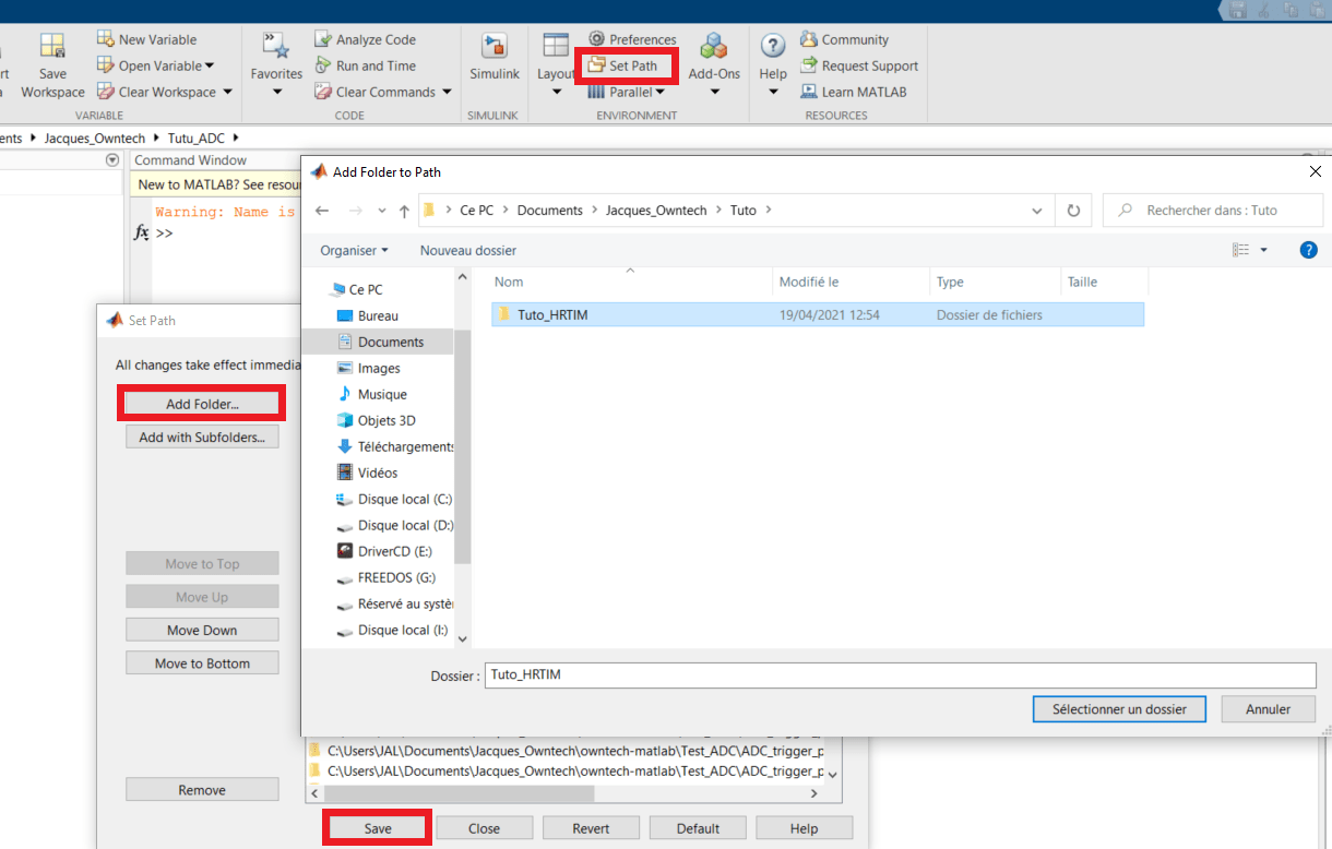
- Open Matlab and add the folder you are working in to your path.
- Make sure that in Matlab you are located in the working folder.
Now you can open your Simulink and change a few parameters with right click and Model configuration parameters (or ctrl + E).
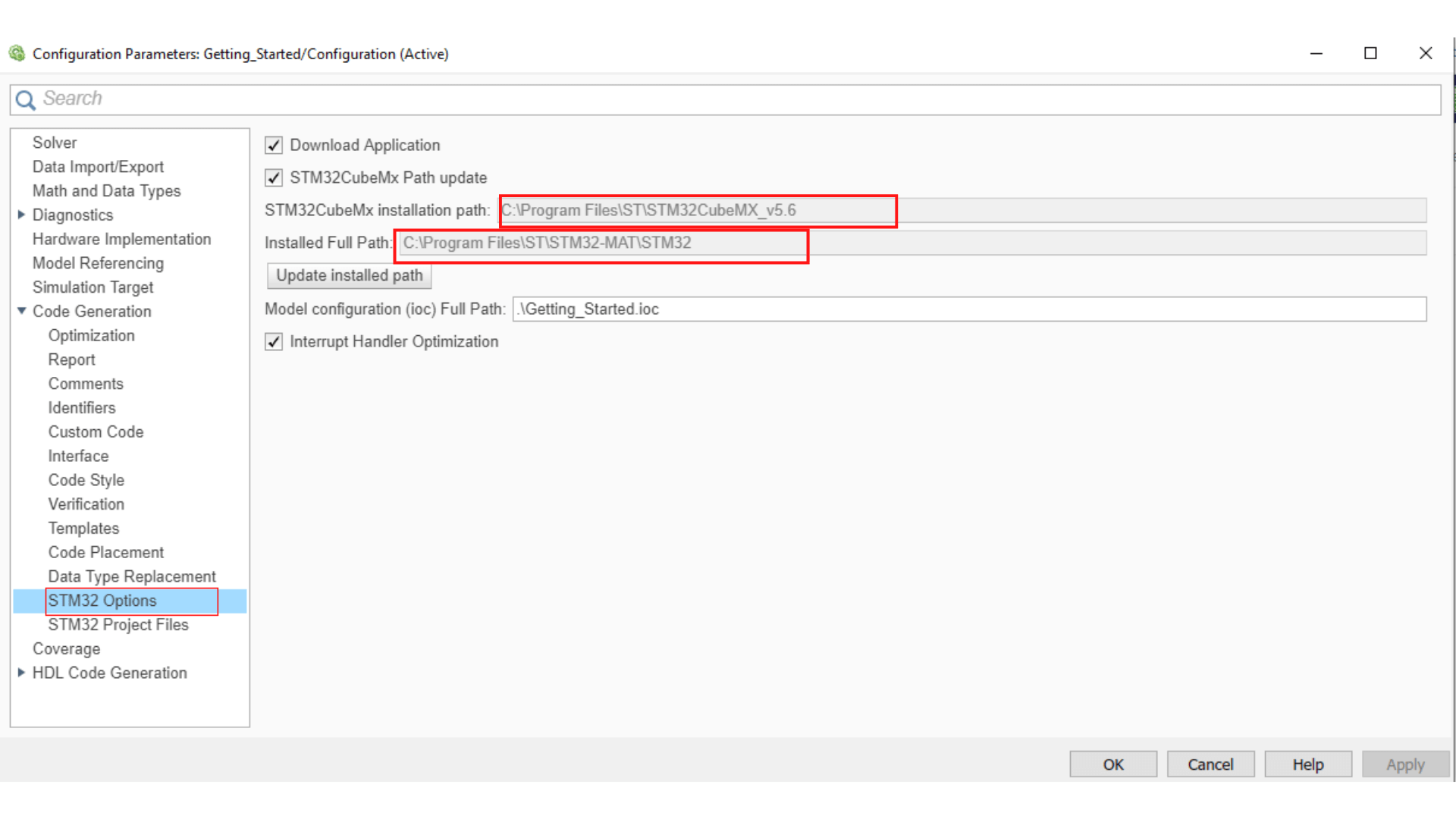
You need to link your .ioc file to the Simulink model, so double-click on the STM32 Config block and choose Select STM32 configuration file then browse to your working folder, select the .ioc file you just configured and then apply.
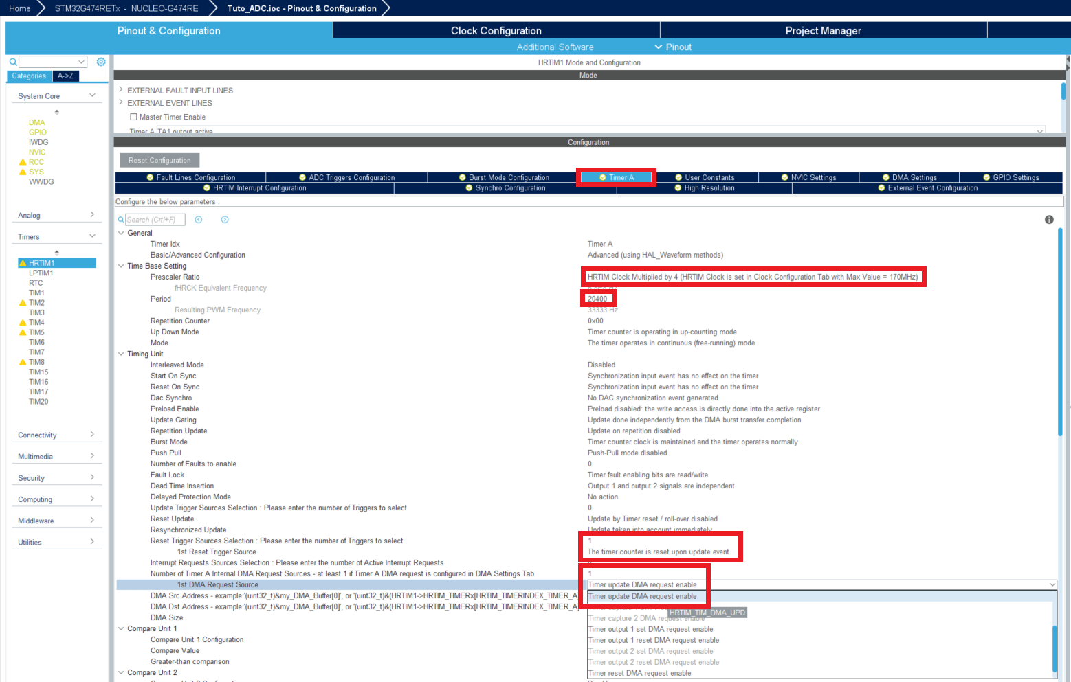
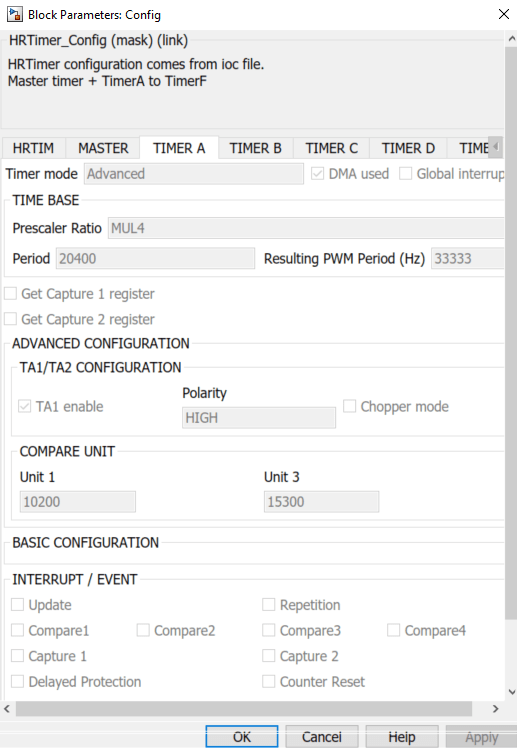
- Now let's check the settings of the HRTIM1 by double clicking on the HRTIM1 config block.
If you haven't these settings, tick and untick a box and click on apply in order to refresh the linking with the .ioc file.
We can see in this window that the period is 54400 counts and Compare unit 1 is 27700 counts, so over a period of 54400 counts, the output will switch from 3.3V to 0V after 27700 counts (approximatively half a period).
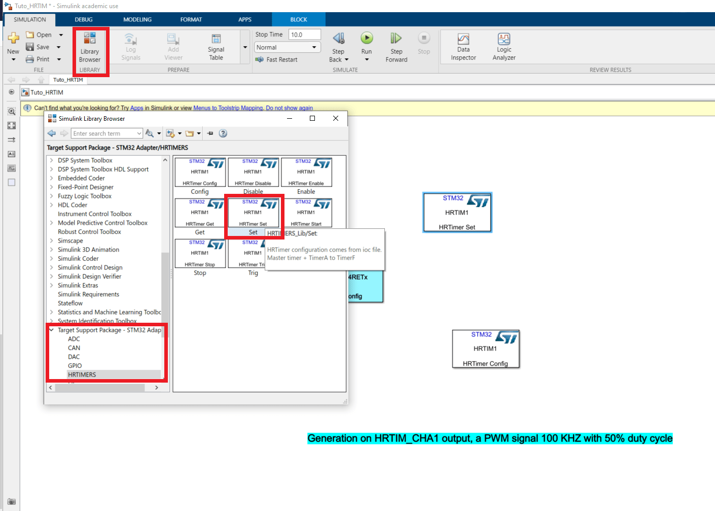
If we want to drive the duty cycle from matlab we need to add a new block : in Library Browser>Target Support Package-STM32 Adapter>HRTIMERS pick a Set block.
- In this block, in the tab Timer A, tick the box Compare1 is an input port, apply and click on ok to shut the window.
Normally an input just appeared on the block.
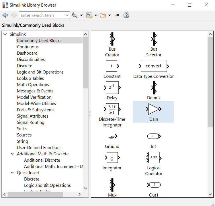
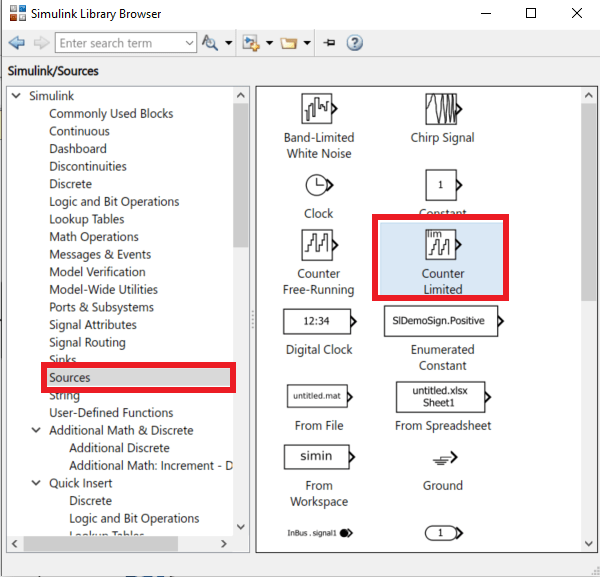
- In the library browser, get a Saturation block, a gain block and a Counter Limited block. They can be found in Commonly used block and Sources.
- In the Counter limited block, set the Upper limit to 5440 and the sample time to 0.001. This means that this counter will count from 0 to 5440 by incrementing every 1ms.
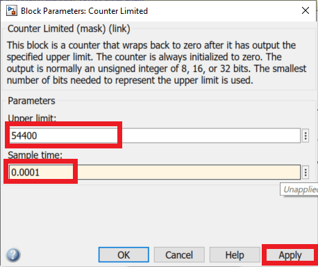
In the Gain block set the gain value to 10.
In the Saturation block, set the Upper limit to 48960 and the lower limit to 5440. These value represent 90% and 10% of the period. Connect the Counter output to the Saturation input.
Now the Saturation output should be a counter from 5440 to 48960 that increments +10 every 1ms. I chose to use a saturation to get this output because in practical cases it is dangerous to set the duty cycle too close to one or zero so saturation blocks commonly used.
Connect the Saturation output to the HRTimer Set block's input. Now the Compare 1 value goes from 10% to 90% of the period count. This means that the duty cycle of the PWM goes from 10% to 90%.
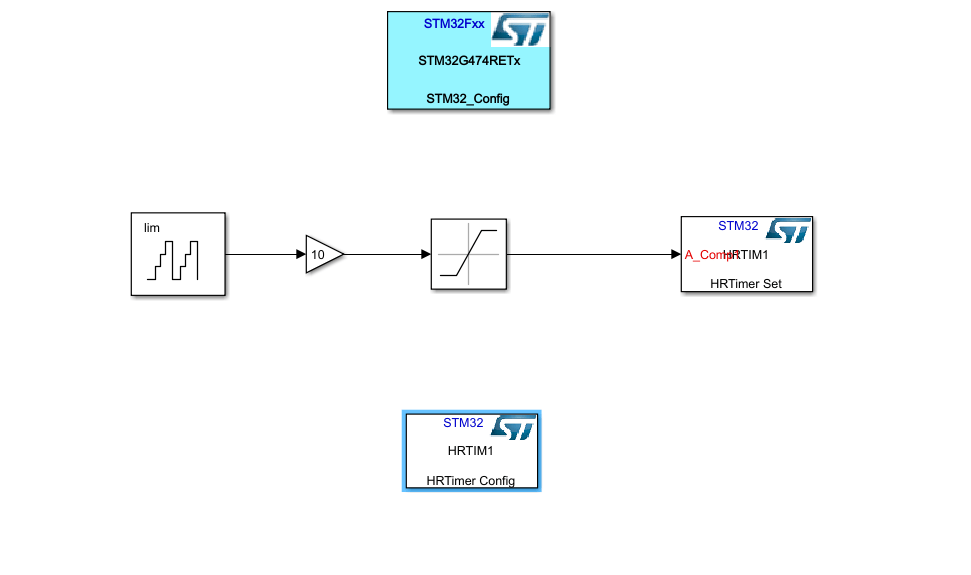
In the end your Simulink model should look like this.
Don't forget to save your Simulink file before generating code
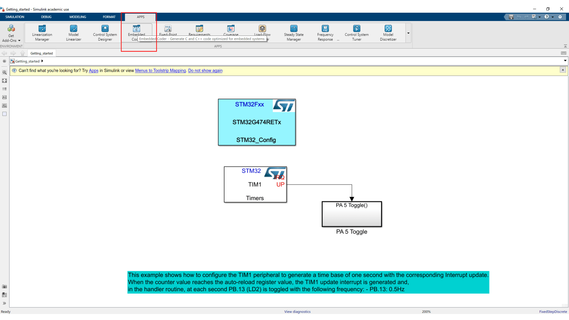
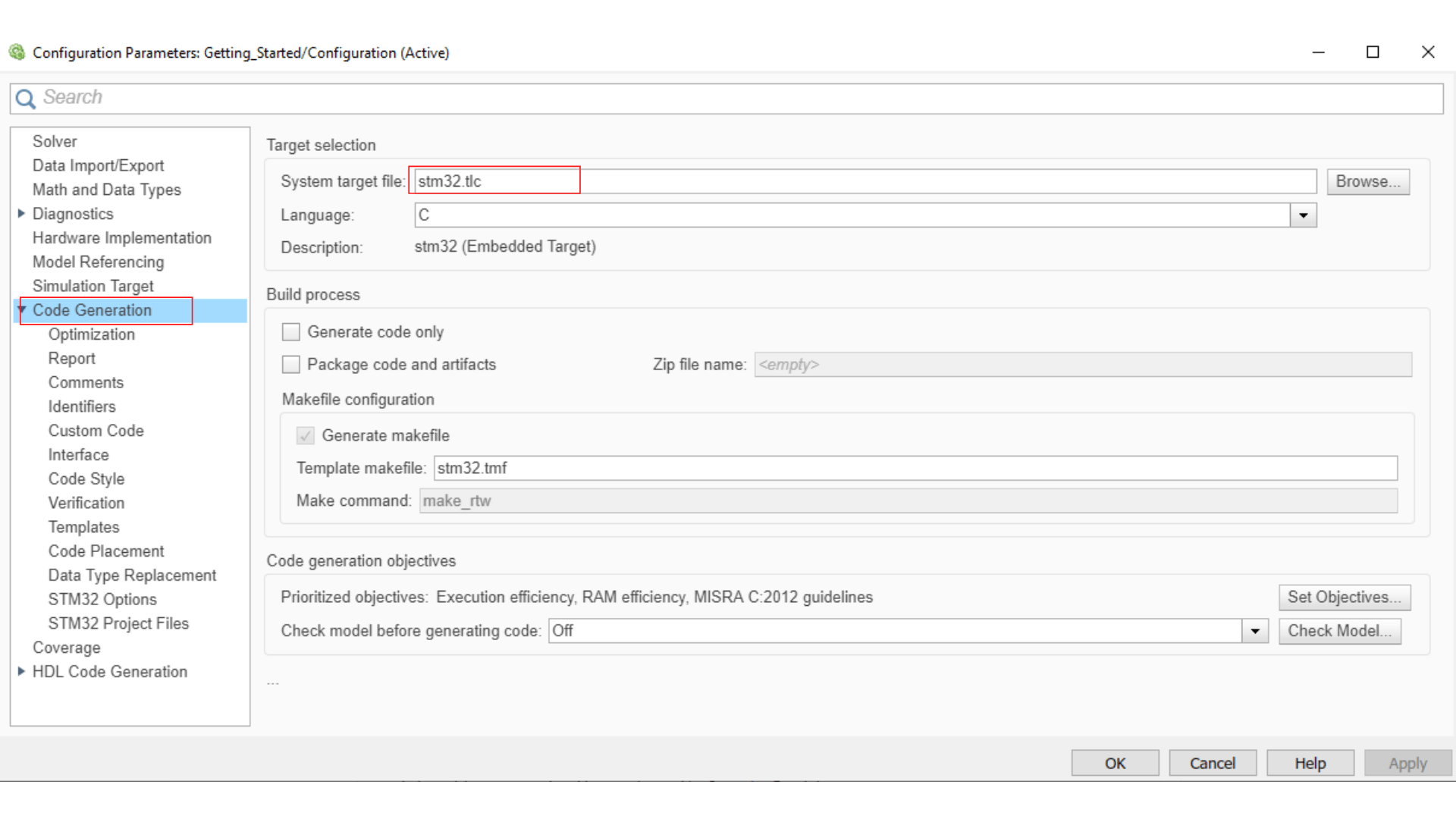
- In the tab APPS choose Embedded Coder this will open the tab C Code in which you can click on Build to generate your code.
Even for this simple example the code generation might take a few minutes.
CubeIDE settings
Launch STM32CubeIDE and select your workplace. If you haven't yet a workplace, create a folder to contain your working folder.
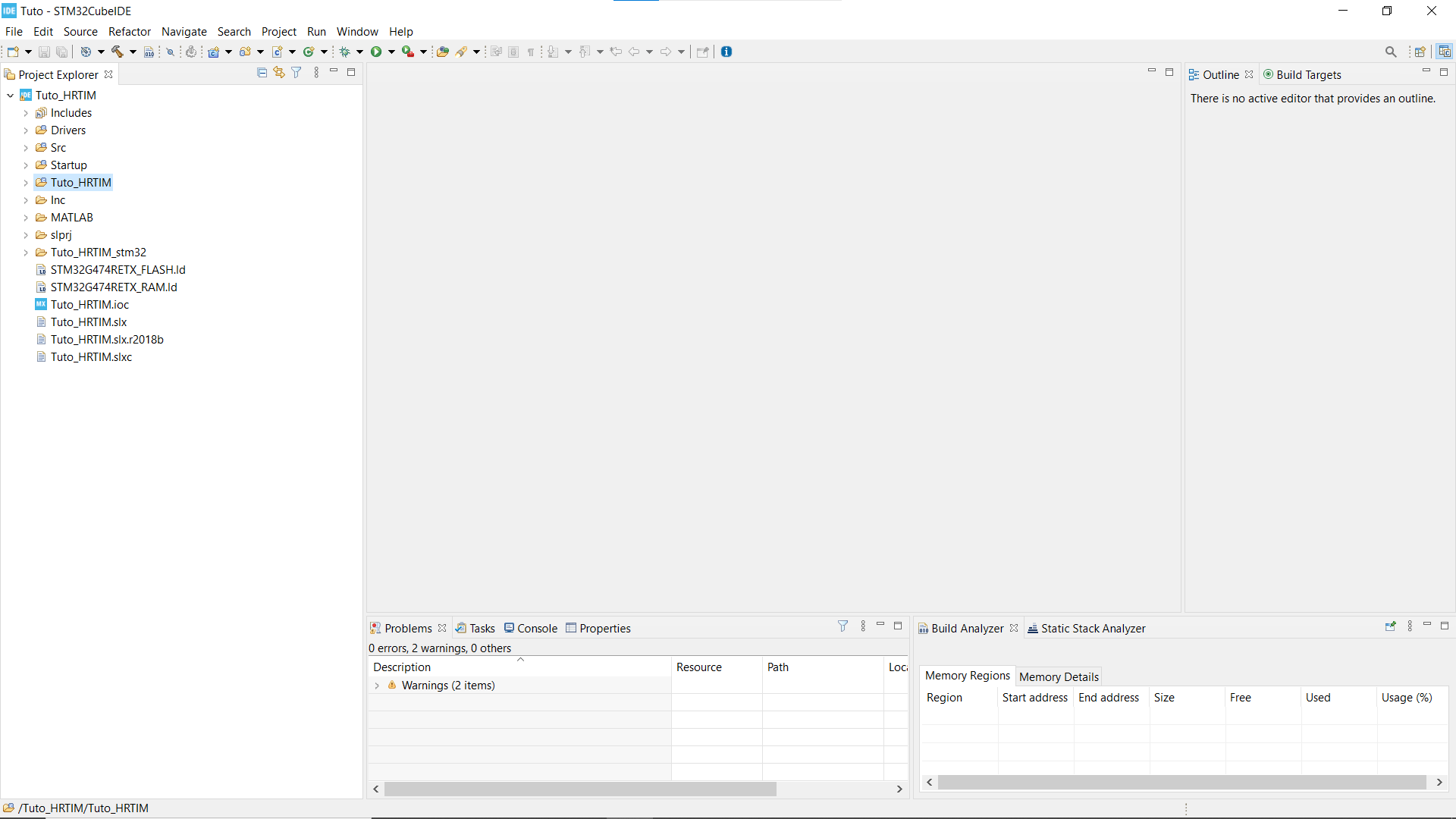
Open your working folder in CubeIDE.
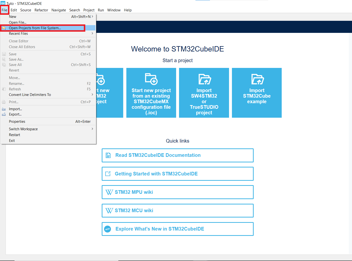
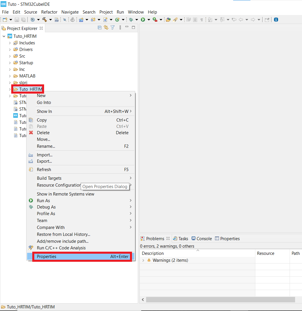
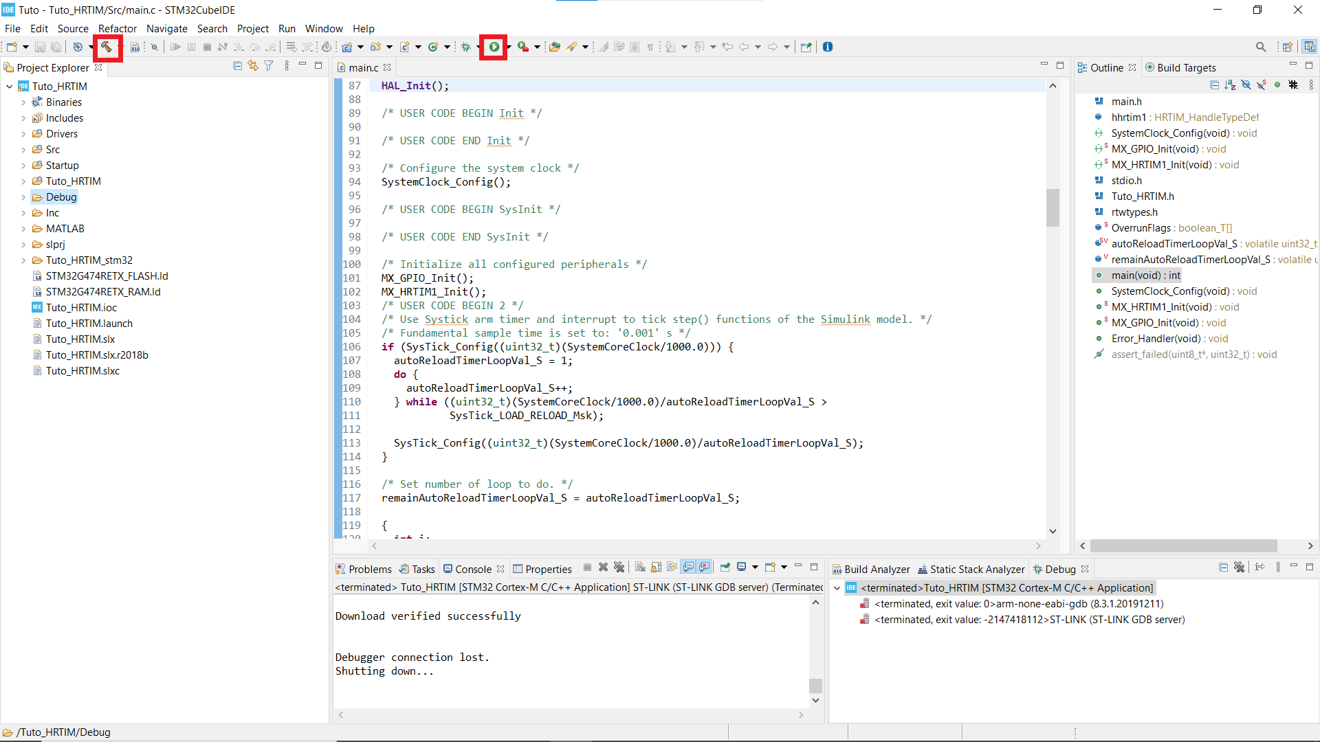
- If you can't see your Projet explorer, shut the Information Center window, so you see something like the second picture.
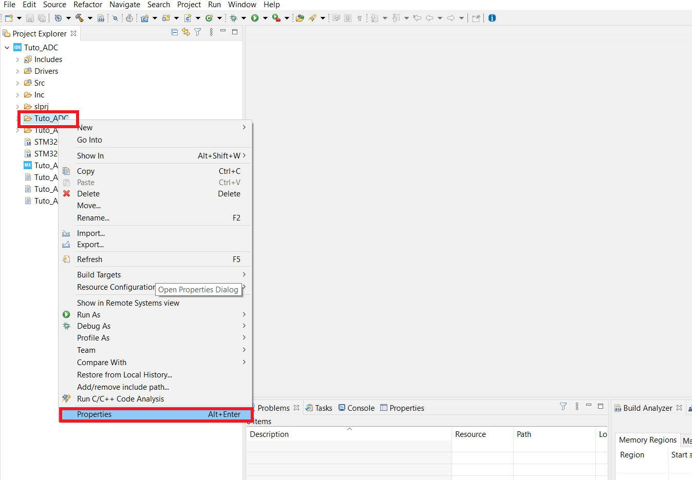
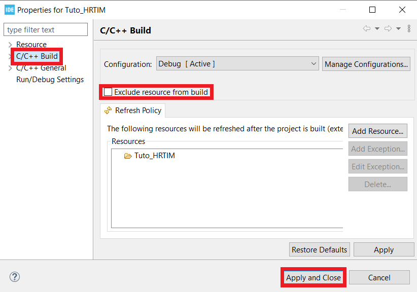
- Find the folder that has the same name as your working folder, right click on it, open the properties window* and in C/C++ Build untick the box that says Exclude resource from build.
- Now your code is ready to be built and implemented.
Observation
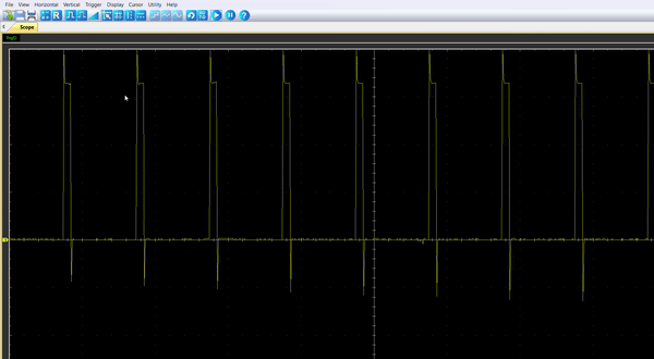
To observe the variable PWM, we need an oscilloscope. In my case, I used a Hantek 6022 BL that can be plugged in my computer via USB. The driver and the application software are free to download.
Once the code is running, by connecting the probe to the pin PA8, you should be able to observe an enlarging PWM that reset every 5.4s.