Contributors
- Romain Delpoux, 2021.11.04
- Loic Queval, 2021.11.05
- Adrien Prévost, 2021.11.05
- Luiz Villa, 2021.11.07
- Antoine Boche, 2021.11.08
Tutorial Communication
The goal of this tutorial is to explore how to define the O2 power converter hardware from software. You will define a measurement, acquire it and show it on the serial monitor. We will start from the Communication Tutorial project.
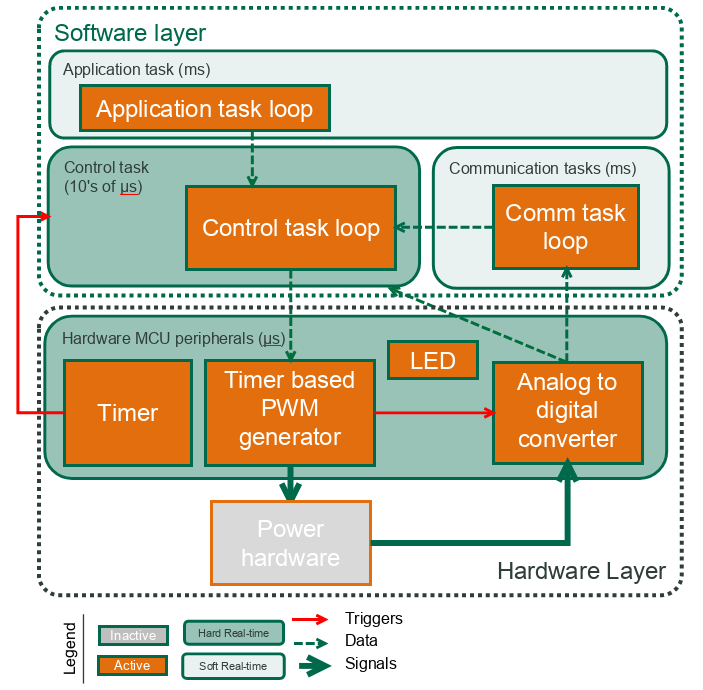
The blocks used in this tutorial are shown in the figure below.
Required hardware
- O2
v_1_1_2 - STLinkV3
- PC (windows or linux)
- power supply (40 V, 2 A)
Create the project
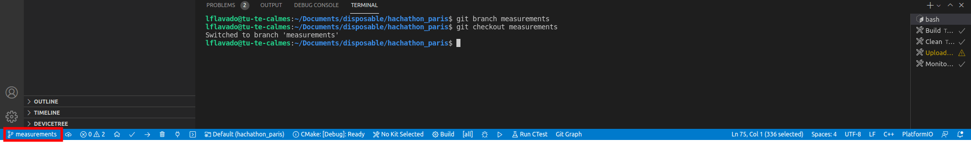
- We will create the project by copying the communication project in a new branch, that will be called measurements. In the terminal,
- On the bottom menu, check that you are now in the measurements branch.
- Check the libraries
In src/main.cpp, check that we load the owntech.ini libraries and the OS drivers:
//-------------OWNTECH DRIVERS-------------------
#include "opalib_pid_voltage.h"
#include "opalib_quick_start.h"
#include "data_conversion.h"
#include "data_acquisition.h"

//------------ZEPHYR DRIVERS----------------------
#include "zephyr.h"
#include "string.h"
#include "drivers/gpio.h"
#include "sys/printk.h"
#include "console/console.h"
- Define the hardware by software !
In src/main.cpp, you will find the setup_hardware() function add the following code to initialize the Analog-to-Digital-Converter with
void setup_hardware(){

    opalib_quick_start_set_hardware_version(v_1_1_2);

    // LED Initialization
    gpio_pin_configure_dt(&led_pin_spec, GPIO_OUTPUT_ACTIVE);

    // MEASUREMENTS DECLARATION
    uint8_t number_of_channels = 1;

    char* adc1_channels[] =
    {
        "V_HIGH"
    };

    // HARDWARE INITIALIZATION
    opalib_voltage_mode_init_hardware(true, adc1_channels, number_of_channels);

}- Define the communication task and the communication menu
In src/main.cpp, the functions setup_communication_task(), loop_communication_task() and menu()remain unchanged.
- Define the application task
In src/main.cpp, add the following code to define the variables that will be used by the application task to print the Vhigh measurement value:
In src/main.cpp, in the function setup_application_task(), do not modify anything. This task will link your application task to a thread which will be executed automatically.
In src/main.cpp, in the function loop_application_task(), add the following code to define the application task. In this example, it will turn the LED on and off depending on the mode chosen by the user. When the led is ON the O2 converter will print the value of Vhigh on the Serial Monitor.
void loop_application_task(void *arg1, void *arg2, void *arg3)
{
    while(1){

        if(mode==IDLEMODE) {
            // application loop in idle mode goes here
            gpio_pin_set(led_pin_spec.port,led_pin_spec.pin,0);

        }else if(mode==POWERMODE) {
            // application loop in power mode goes here
            gpio_pin_set(led_pin_spec.port,led_pin_spec.pin,1);
            printk("Vhigh value: %f \n", Vhigh_value);
        }

        k_msleep(100);

    }
}- Define the control task
In src/main.cpp, in the function setup_control_task(), add the following code to setup a control task. These lines initialize the loop_control_task, define its duration and setup some parameters we will look into later and that we will simply set at 1 for now. The last line activates the timer, launching the control task.
void setup_control_task(){
    // control loop setup goes here
    uint32_t control_task_duration = 50;

    opalib_quick_start_init(loop_control_task, control_task_duration);
    opalib_pid_voltage_init_buck(1, 1, 1, 1, control_task_duration);
    opalib_quick_start_launch_task();
}
In src/main.cpp, in the function loop_control_task(), add the following code to define the control task loop. This loop will acquire the data we want to display, convert it from raw bit values into Volts and store it into a variable that can be accessed by the application task.
void loop_control_task()
{
    if(mode==IDLEMODE) {
        //control loop code when in idle mode goes here

    }else if(mode==POWERMODE) {
        uint32_t v_high_count; //creates a variable that receives the number of measurements that are returned by the low-level api

        // Creates a buffer that receives the data from the data acquisition module
        uint16_t* v_high_buffer = data_acquisition_get_v_high_values(&v_high_count);

        if (v_high_count){ //if data was received it gets converted
            uint32_t raw_value = v_high_buffer[v_high_count - 1];
            Vhigh_value = data_conversion_convert_v_high(raw_value);
        }
    }
}- Connect hardware
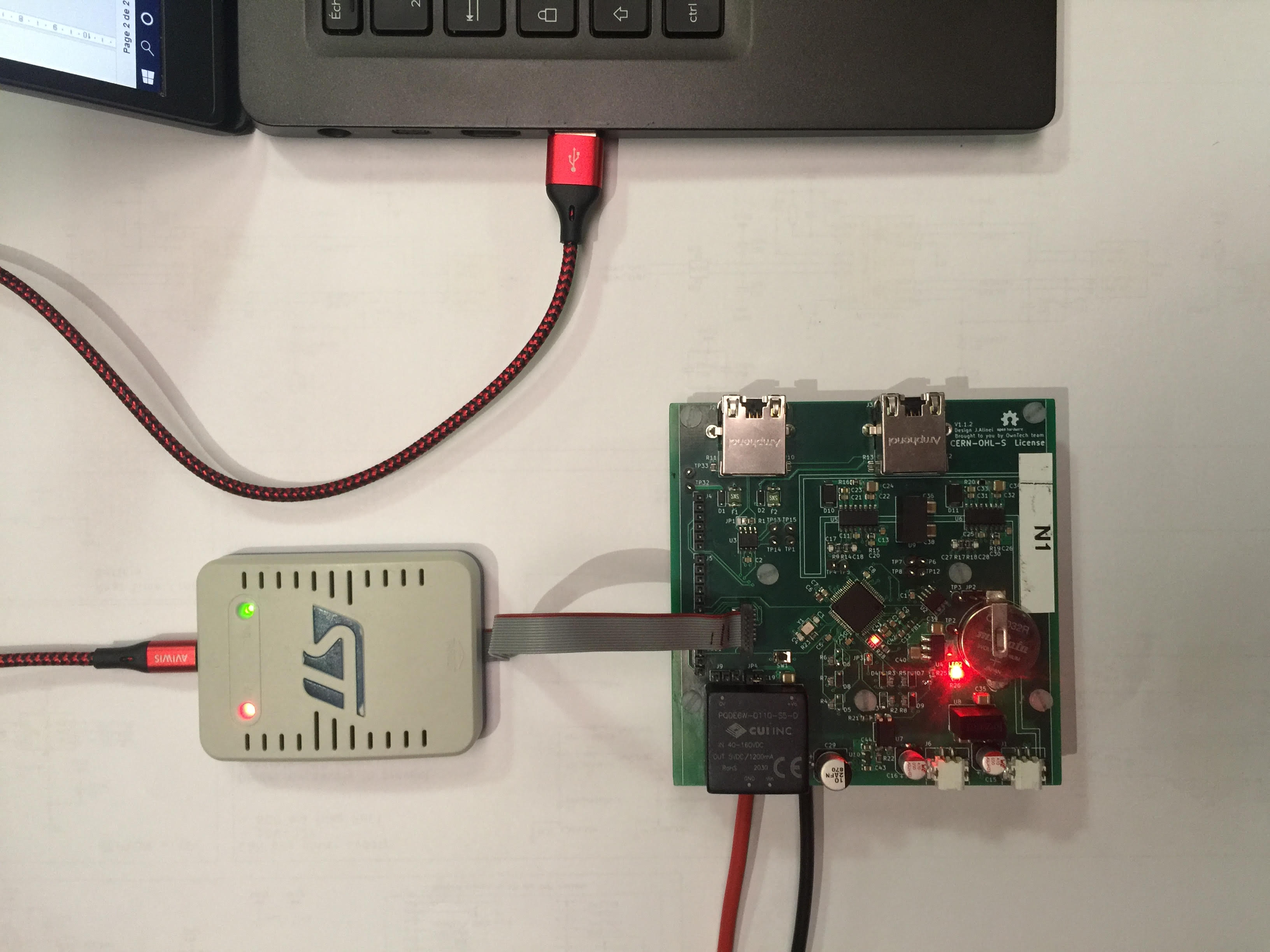
Now we will connect OwnTech’s O2 to the power supply and to the PC.
- Connect the pins Vhigh and GND of the O2 to the 40 V power supply (set the current limitation at 1 A).
- Connect the micro-JTAG connector of the O2 to the PC thanks to the STLinkV3. The leds PWR and COM should be ON.
- Switch on the power supply. The led2 of the O2 should be ON.
In the bottom menu, click on the Build icon
 . This will launch the compilation of the code. When the compilation is completed, you should see [SUCCESS] in the terminal.
On the bottom menu, click on the Upload icon
 . This will flash the compiled code on the microcontroller of the O2. When the process is completed, you should see [SUCCESS] in the terminal.
On the bottom menu, click on the Serial Monitor icon
 . Should print you a menu for you at first. When you press the
 pbutton on your keyboard, the LED will turn ON and the Vhigh data will show on the termina. Hit theibutton to turn it the LED OFF and stop the data display.
Expected outputs
- The led1 of the O2 should start as off.
- The led1 of the O2 should turn on when you press the
pbutton. - The led1 of the O2 should turn off when you press the
ibutton.
That’s it!